
Background
For those readers who want more information on the process I used to design the drive mechanism for my turntable project, read on.
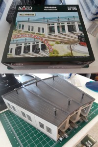
The KATO roundhouse has three stalls whose centerlines are spaced 10 degrees apart. We want the stepper mechanism to be able to precisely line up with these three tracks, but to do that the mechanism’s steps per revolution must be a multiple of (360° ⁄ 10°) or 36. None of the stepper motors’ step counts divide evenly by 36, so I need to use a gear or pulley mechanism to change the steps per revolution at the turntable side.
There are three variables which I can adjust to set up the gearing ratio:
- Number of steps per revolution of stepper motor
- Diameter of motor’s pulley or number of teeth in its gear
- Diameter of turntable’s pulley or number of teeth in its gear
To prevent slippage from causing errors in the turntable’s positioning, I am using a toothed belt to connect the motor and turntable, so I have to select the tooth counts of two gears. The belt is an MXL belt which has a pitch (distance between teeth) of 0.08 inches. I also have three sizes of small MXL-compatible toothed pulleys to choose from for the motor side, 18 and 32 tooth pulleys for 4 mm motor shafts plus 20 tooth ones for 5 mm shafts.
For the stepper motor, I have three different stepper motors on hand. (Actually four, see notes below.)
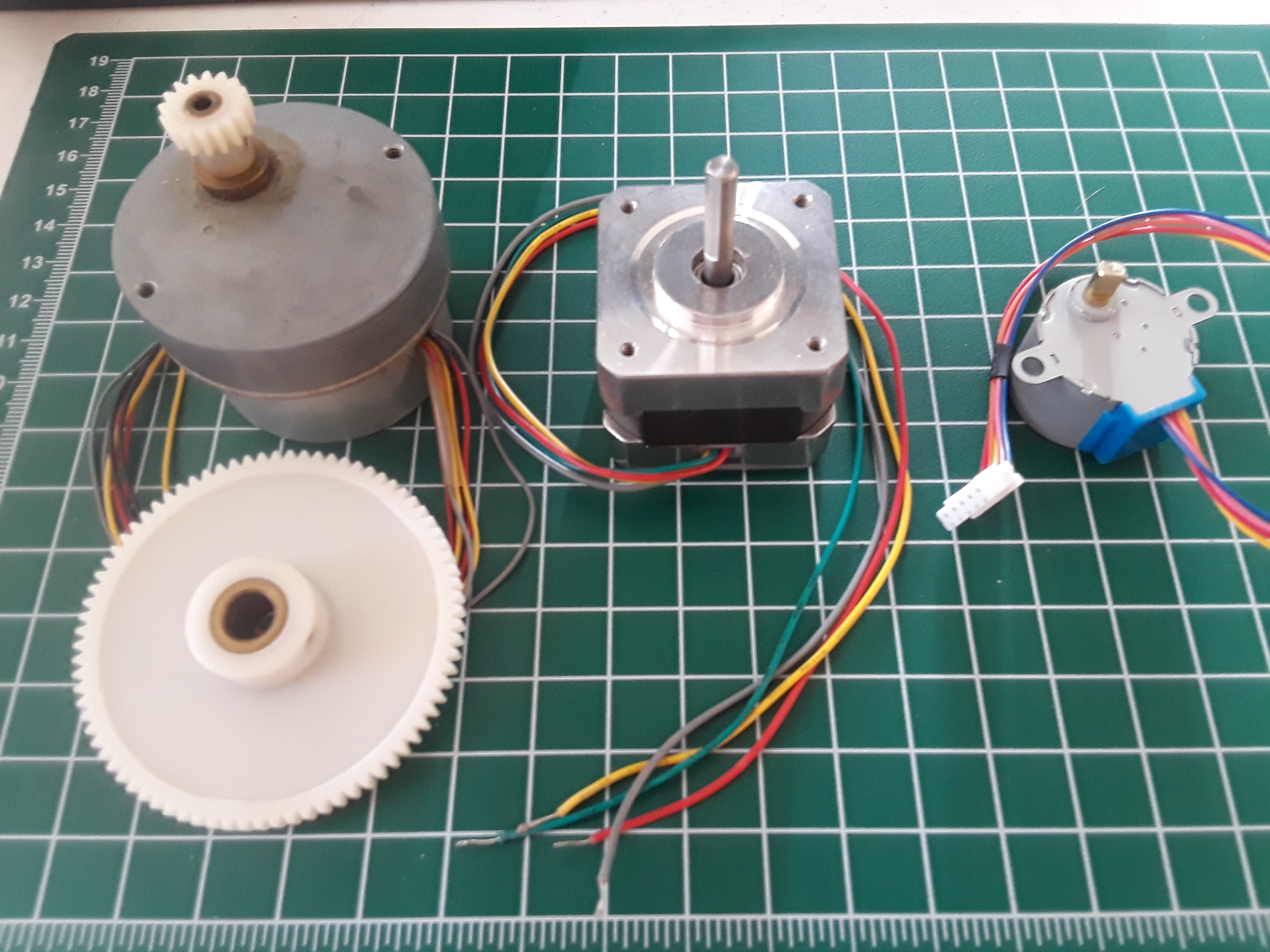
From left to right in Figure 2:
- An 8-wire geared stepper motor with 480 steps per revolution, with a pair of external gears I could use to change the effective resolution to 2400 steps per revolution, or 0.15 degrees per step. Unfortunately, I’ve had this motor for at least 35 years and no longer have the wiring diagram, and it’s too old to be found on the internet. It’s also quite heavy for its size.
- A newer 4-wire NEMA-17 stepper motor with 200 steps per revolution. Also a bit large and heavy. This motor and the 8-wire one are both designed to be driven with 12 volts. NEMA-17 steppers are commonly used in 3D printers and CNC machines. I got mine from Adafruit.com.
- A 5-wire geared stepper with 513(!) steps per revolution. This particular device is available both in 5 volt and 12 volt versions from Adafruit.com. Mine is the 5 volt unit.
NOTE: It turns out the stepper motor which was advertised as having 513 steps per revolution is now listed as having 516 steps. Other text on the vendor’s current web page for that motor makes me believe the new number is incorrect. However, several message threads in the company’s online forum state that the same motor with the same part number in fact gets shipped with a variety of step counts, depending on the particular gears installed inside, with no labelling to identify the actual counts. Therefore I can’t trust that small motor for my project.
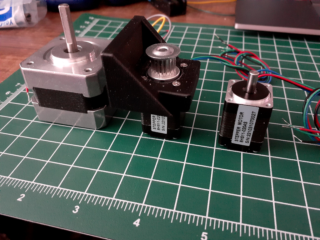
ANOTHER NOTE: I’ve since found an even better stepper motor for this project, a 5 volt NEMA-8 motor which will actually fit inside the T-TRAK module which will hold the turntable; the NEMA-17 motor in its mounting bracket turned out to be physically too large to fit inside the module. The smaller motor also has a 4 mm drive shaft rather than the NEMA-17’s 5 mm shaft, so I will be using an 18-tooth pulley gear with it. Below is a picture of the original NEMA-17 stepper motor with two of the NEMA-8 motors, one of which is installed in a test version of a 3D-printed mounting adapter, and with its pulley gear on the motor shaft.
Calculations
To get the smallest steps possible on the turntable side, we want the motor resolution high, the motor’s drive gear small, and the turntable’s gear large. Let’s call the number of teeth in the motor’s small gear SG, and use LG for the turntable’s larger gear.
Obviously both SG and LG are whole numbers, because you can’t have fractional teeth in a gear. But the gear ratio GR = (LG ⁄ SG) can be fractional; a 3:2 or 1.5 gear ratio would be perfectly reasonable. Let’s also use SC for the motor’s step count per revolution. So if we connect a gearing mechanism to our motor, we can move the turntable with a new step count TC = SC × GR = SC × LG ⁄ SG. It’s TC that we now want to be a multiple of 36 to match the roundhouse dimensions.
I can’t find any larger gears for the turntable side which are compatible with the timing belt and have high enough tooth counts to give me a usable TC, so I will 3D-print a custom one with the number of teeth I want. So how many teeth do I want?
The step count SC is either 480, 2400, 200, or 513, depending on which motor I use, and in the case of the old 480-step motor, if I include the external 5:1 pair of gears. More steps is better, you would think. We define SG to be 18 for a 4 mm shaft motor. TC must be a multiple of 36, so I need to find suitable values for LG, the number of teeth in the turntable’s larger gear.
I have two more constraints I need to consider. First, my 3D printer’s print surface is 220 mm square, or about 8.7 inches in the X and Y directions. So I can’t create a large gear which won’t fit within this area. Also, I need the turntable’s step angle to be (much) smaller than the width of the rail heads at the ends of the turntable’s bridge, so that I can fine-tune the positions where the turntable will need to align with the tracks around its perimeter.
Most N-gauge track uses rails which are 0.025 inch or 0.635 mm thick at the top (the rail head). The turntable bridge is 151 mm long, so the radius is half that or 75.5 mm. So the end of each rail sweeps an angle of (0.635 ⁄ 75.5) ≅ 0.0084 radians ≅ 0.48°. I want the angle moved for each turntable step to be a fraction of that angle, say 0.10°. That will require a larger gear ratio to reduce the turntable step size, but not so large that the gear becomes too big for the printer.
After a few failed attempts at finding workable gear ratios caveman-style (pencil and paper), I finally wrote a Python program which lets me set the initial parameters, and it then searches for sizes of the large gear which meet all my constraints. You can find the source code at the bottom of this page.
I ran the Python code using an 18-tooth small gear and the 200-step NEMA-8 motor, and I found the following 3 possible solutions.
Large Diameter Diameter Gear   Step   Steps/ Total Railhead
 Gear   (mm)     (in)   Ratio  (deg)  Stall  Steps Fraction
----- -------- -------- ------ ------ ------ ----- --------
   81     52.4     2.06  4.500 0.4000     25   900   0.9583
  162    104.8     4.13  9.000 0.2000     50  1800   0.4792
  243    157.2     6.19 13.500 0.1333     75  2700   0.3194
I can actually improve on these numbers by driving the 200-step motor with microstepping, using a motor driver which can power the two coils of the stepper motor with sine-wave-like voltages 90 degrees apart in phase. The actual drive voltages could be pure analog or PWM (pulse-wave modulated) digital voltages. The driver I have designed is built around an L293D quad half-H-bridge driver chip, using Arduino code which approximates sine-wave voltages using PWM on four microcontroller outputs. The new driver has been tested in 1/8-step mode, so the motor moves as if it were a 1600-step motor instead of 200. Running the same calculations with 1600 steps instead of 200 gives me these solutions.
Large Diameter Diameter Gear   Step   Steps/ Total Railhead
 Gear   (mm)     (in)   Ratio  (deg)  Stall  Steps Fraction
----- -------- -------- ------ ------ ------ ----- --------
   81     52.4     2.06  4.500 0.0500    200  7200   0.1198
  162    104.8     4.13  9.000 0.0250    400 14400   0.0599
  243    157.2     6.19 13.500 0.0167    600 21600   0.0399
Based on these results, I am planning to 3D-print a 243-tooth gear with the same tooth pitch as the motor’s small gear, which will give me very fine steps compared to the width of the railheads.
Python code
Below is the Python 3 script I used to search for valid combinations of gear sizes and stepper motor step sizes to work on my railroad turntable project. This script can also be downloaded from my GitHub repository at https://github.com/twrackers/Turntable-sketches/blob/main/Python/turntable.py.
import math

# Script update 2018/9/21 by Thomas W Rackers
#   Improved formatting of results.
# Script updated again 2020/4/23
#   Even better formatting of results. 🙂
# Script updated again 2022/3/11
#   Use .is_integer() method.
# Script updated 2022/06/26
#   Update rail_width with value from KATO web site.
# Script updated 2022/11/26
#   Changed stepper_count to new value for 1/2 micro-stepping.
# Script updated 2023/2/11
#   Changed stepper pulley gear size from 18 to 20 teeth.
#   Increased precision of displayed gear ratio.
#   Added column for total steps per rotation.
# Script updated 2023/2/19
#   Changed stepper pulley gear size back to 18 teeth.
#   Changed stepper_count for 1/2 micro-stepping.
# Script updated 2023/3/28
#   Changed stepper count for 1/8 micro-stepping with new driver h/w.

def in_to_mm(v):
    return v * 25.4

def mm_to_in(v):
    return v / 25.4

def make_gear(pitch):
    return lambda x: x * pitch / math.pi

# Adjustable parameters
stepper_count = 1600  # stepper counts/revolution,
                      # using 1/8 microstepping
small_gear = 18       # tooth count on small pulley

# Fixed values
num_stalls = 36
roundhouse_delta = 360 / num_stalls  # angle between stalls, degrees
belt_pitch = in_to_mm(0.08)  # MXL belt pitch, mm
rail_width = 0.55  # KATO N gauge rail head width, mm
rail_length = 151  # rail length, mm
max_dia = 200  # max large gear diameter, mm
# Diameter limited by 3D printer print volume.

# Define belt gear generator with known belt pitch.
gear_dia = make_gear(belt_pitch)
# gear_dia(teeth) will return diameter in mm.

# Angle between stepper steps, degrees
stepper_delta = 360 / stepper_count

# Effective diameter of small gear, mm
small_gear_dia = gear_dia(small_gear)

# Arc width of rail end, degrees
rail_arc = math.degrees(rail_width / (rail_length / 2))

# Header and format strings
hdr1 = "Large Diameter Diameter Gear   Step   Steps/ Total Railhead"
hdr2 = " Gear   (mm)     (in)   Ratio  (deg)  Stall  Steps Fraction"
hdr3 = "----- -------- -------- ------ ------ ------ ----- --------"
fmt = "{:5} {:8.1f} {:8.2f} {:6.3f} {:6.4f} {:6} {:5} {:8.4f}"

# Print header.
print(hdr1)
print(hdr2)
print(hdr3)

# Try sizes for large gear from small gear's size up.
for large_gear in range(small_gear, 20 * small_gear):
    # Stop if we will exceed 3D printer capacity.
    large_gear_dia = gear_dia(large_gear)
    if large_gear_dia > max_dia:
        break

    # Calculate the gear ratio.
    gear_ratio = large_gear / small_gear
    # Calculate the turntable's step size (degrees).
    turntable_delta = stepper_delta / gear_ratio
    # If the turntable steps are not less than the arc of
    # the end of a rail head, skip this one.
    rail_widths = turntable_delta / rail_arc
    if rail_widths > 1:
        continue

    # Calculate number of steps between roundhouse stalls.
    roundhouse_steps = roundhouse_delta / turntable_delta
    # Number of steps must be a whole number.
    rounded_steps = round(roundhouse_steps, 2)
    if rounded_steps.is_integer():
        print(fmt.format(large_gear, large_gear_dia,
                         mm_to_in(large_gear_dia), gear_ratio,
                         turntable_delta, int(rounded_steps),
                         int(rounded_steps * num_stalls),
                         rail_widths))
