
Background
Most people who get a model train start out with a simple loop of track. Even if the actual shape of the track becomes convoluted with crossings and elevated tracks passing over other tracks… as long as a train starts out at any point, travels over the entire path of the track, and comes back to the starting point from the direction opposite the way it departed, it’s a loop. The most common single-track alternative is the point-to-point layout; the track plan shown on this site’s Overview page is point-to-point, with one passing section.

- Two simple track loops

Plenty of fun can be had with such layouts… unless you want to operate more than one train at the same time on the track. You see, the entire track (ignoring any turnouts for just a moment) is electrically one circuit. If you put two motor cars (locomotives, trams, etc.) on the track at the same time, when the track is powered both motor cars will move, and in the same direction. So if you’re the type of person who wants to collide your trains head-on… sorry, it’s not going to happen.
What will happen, however, are two things:
- You will be drawing roughly twice the current from your throttle. This might be enough to trip your throttle’s internal circuit breaker, assuming it has one. (Nearly all do.)
- One of your motor cars will almost certainly run faster than the other one, so it will eventually rear-end the slower one. Minimal fun to be had there either.
There are two ways around this problem.
- Equip your motor cars with DCC (digital command control) decoders, and replace your DC throttle with equivalent DCC hardware. DCC is pricey and complex, but many model railroaders successfully use it all the time. But this option holds no appeal for me personally.
- Divide your track into electrically isolated blocks, where each block can be selectively connected to one of several independent throttles. Then all you need to do is energize with one throttle the track block where your motor car is, and probably the next one in the direction it’s traveling. If you have multiple blocks and multiple throttles, you can run as many trains as you have throttles. Sounds simple, no?
No, it’s not, if you have to switch the track power manually as your train moves from one block to the next. But if you can let a computer (a) sense the location of your train, (b) control the power to drive the train, and (c) route that power to the desired block(s) on the layout, you’ve got the basics of a computer-controlled model railroad setup. And that’s precisely what I’m working towards here.
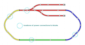
- Track layout divided into blocks

To the right is a simple layout divided into four blocks, with each block’s power feed highlighted. In theory, with a pair of throttles you could keep two motor cars running at the same time, as long as the power from each throttle is always routed to the block where the motor car is, as well as the next block before the motor car reaches the boundary between the blocks.
Note that each block’s power connection can be anywhere within the block… with one major exception.
What about those turnouts?

- Sample turnouts (KATO Unitrack)
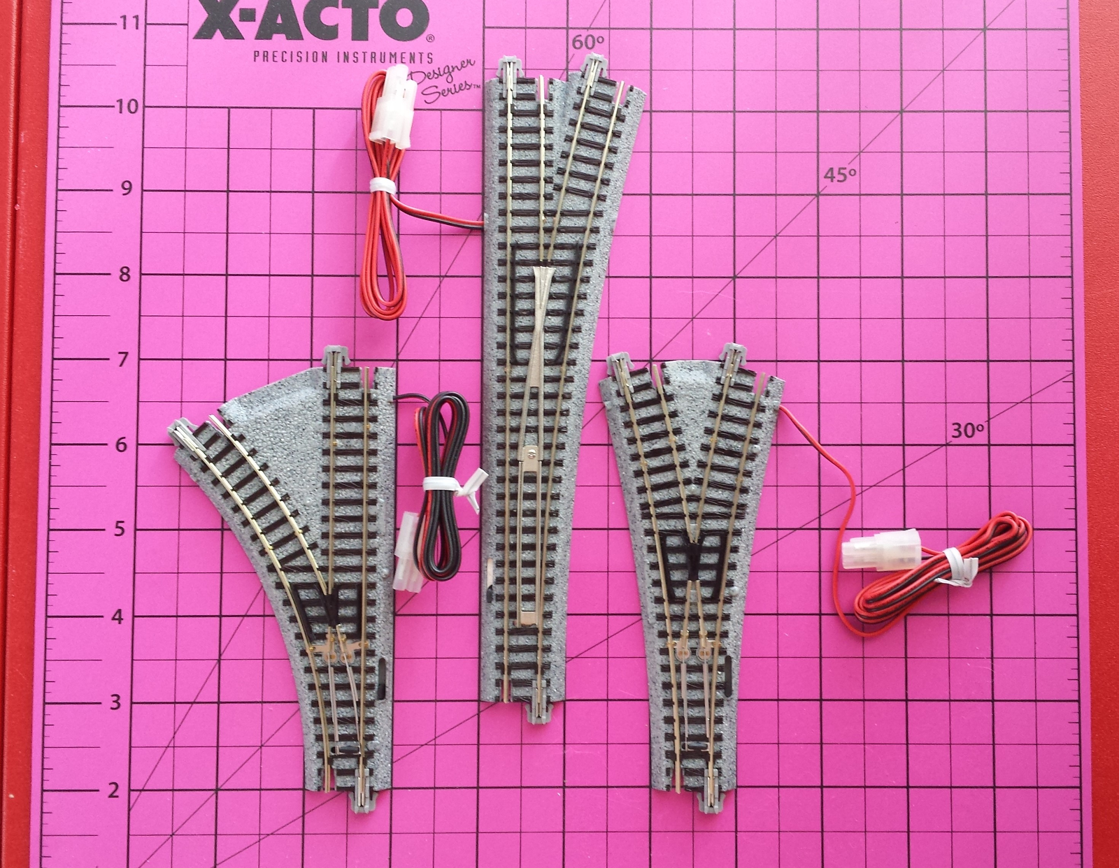
Ahhhh… turnouts make things a little more interesting.
Your basic turnout resembles a letter Y, usually (but not always) with one path from top to bottom being straight and the other curving off to the left or right. The bottom of the Y, or the part of the track common to both paths, is the point end of the turnout. (In some countries, the term point is used instead of turnout or switch.) The straight leg is often called the main route, and the curved one is usually the diverging route. For our purposes though, the main and diverging routes are equivalent.

- Power-routing turnouts
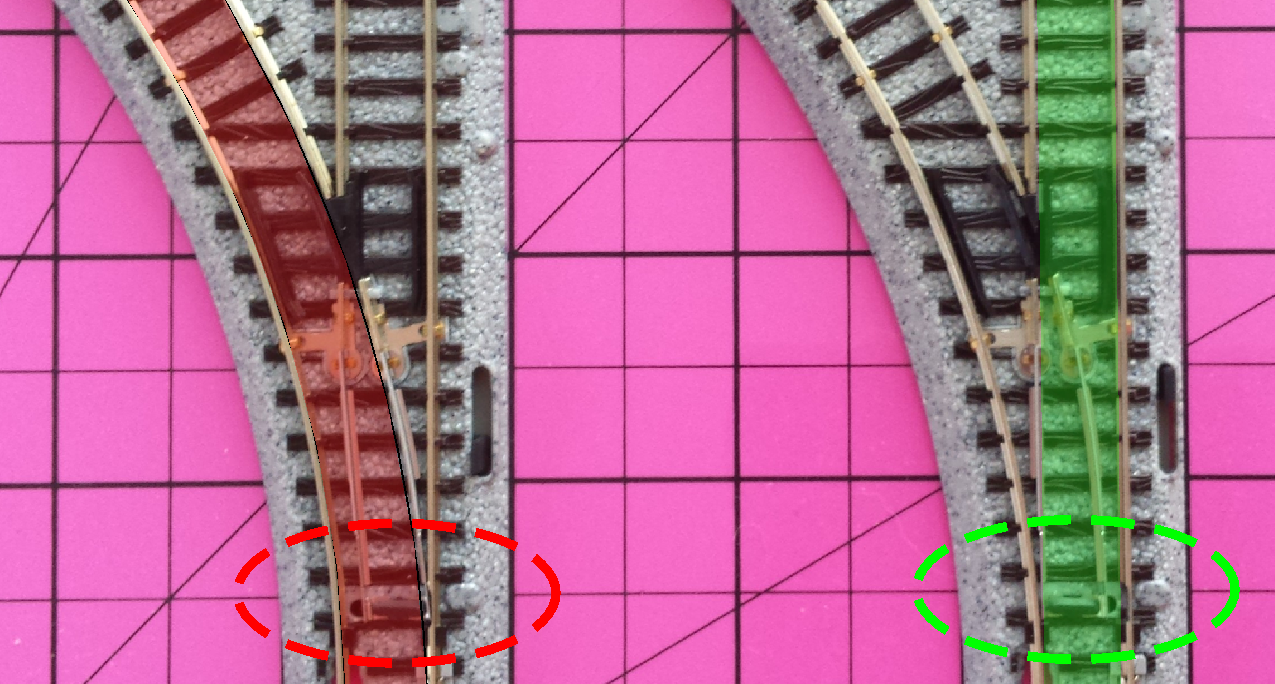
Model train turnouts come in two flavors, power-routing and non-power-routing. Simply put, a power-routing turnout will electrically connect the point end to exactly one of the two other ends, main or diverging; both will never be connected at the same time. In the picture to the right, you can see how the position of the points (inside the dashed ellipse) determines through which route the turnout will carry power.
By using power-routing turnouts in the track plan above, the main line and both sidings at the top can be a single block sharing a power feed connection. You could have a motor car on each of the three tracks, and only one would receive power from the throttle, depending on which way the two turnouts are thrown. You could make either or both sidings separate blocks, but you don’t have to.
By the way, the power-routing turnouts in the track plan above force you to make the red block’s power connection on the point end of both turnouts as shown. This is the one major exception to the connect-anywhere-you-want-in-the-block rule.
Non-power-routing turnouts will always have all three ends connected together electrically. Non-power-routing turnouts work better for DCC, but not for this project.
Special note: some turnouts can be configured to be either power-routing or non-power-routing; some of KATO’s turnouts fall in this category.
Switching a single block
Suppose you have a block of track for which you’d like to select which one throttle of several should be controlling any motor car within its boundaries. You’d probably want some form of switch which will connect both rails to one throttle at a time (or perhaps none sometimes). In electrical switch terms, you want a double-pole N-throw switch, where N is how many throttles you want to select from. If you want no-throttle as an option, that counts as a throttle choice too, just an unconnected one. Commonly seen switches are DPST (double-pole single-throw) and DPDT (double-pole double-throw). A DPDT switch would be useful if you only have two throttles, but what if you have more than two?

- Single block with switched power

The solution I am using is to create a DP{many}T switch using an array of DPST relays. This will not only allow me to use as many separate throttles as is practical (for this project, either 4 or 8), but it also lends itself directly to being operated by computer control.
In the drawing on the right, the orange line shows that only one relay, the middle one, is being energized, closing its contacts. That means the track block is connected only to throttle 2. In order to make this work, for every block, only one relay (if any) can be closed at a time.
Switching multiple blocks
So far so good. Now how do you apply relay switching to our multiple-block layout?
All you need to do is duplicate the single-block design above for each block. All relay banks will share their throttle-side connections, so any throttle at any time can be connected to no blocks, all blocks, or anything in between. Remember though, each block can be connected to only one throttle at a time, or none of them. One throttle can be connected to many blocks, but one block can only be connected to at most one throttle.

- Relay matrix, 3 throttles to 3 blocks

So now we have not an array of relays, but a relay matrix. By the way, you’re free to connect any block’s relays to only some of the throttles, if there are for example some blocks reserved for switching operations where you never want to connect them to a throttle you’re using only for main-line running. It’s up to you.
Hardware
Block addressing logic

The diagram above shows the overall design of the block switching logic, starting from the control processor’s I2C central port on the left and ending at the collection of active-low drive signals to the relay modules’ coils. Each part pair on the right, M74HC238 and ULN2803A, selects one throttle connection out of up to 8 for a single block.
The portion outlined in red will support a smaller layout with up to 8 x 4 or 32 blocks switching up to 8 throttles, assuming the control processor’s I2C is connected to the MCP23017 devices’ inputs. For a larger layout, the TCA9548A I2C multiplexers on the left can expand the control processor’s single bus into up to 8 x 8 or 64 separate buses, expanding the layout to support up to 64 x 32 or 2048 blocks.
More details are in the sections following.
Relay decoder/driver
To drive the relays for a given track block, a decoder/driver circuit provides the interface to the controlling processor. The schematic below shows the design I am using.

- Relay decoder/driver schematic
The IC on the left is a 74HC238 3-to-8 decoder. It takes 3 logic signals, A0 through A2, which select which relay of a block of 8 should be activated. If all three are logic low, output Y0 will go high; if all are high, Y7 will go high. So signals [A2, A1, A0] form a binary value from 0 through 7, and the Y output matching that value will be the only one which goes high; all the other Y outputs remain low. This is how the only-one-relay-per-block requirement is enforced.
The signal labeled ALL_OFF must be held low to allow the decoder to assert any of the Y outputs. If ALL_OFF is high, all Y outputs are forced low, turning off all relays in the block.
The ~BUS_DISABLE signal is similar to ALL_OFF, except it must be held high to allow decoding to occur. Also, this signal will be common to ALL blocks, so if it is pulled low, all blocks will be disabled.
The IC on the right is a ULN2803A 8-channel driver chip. Each channel contains a Darlington transistor which turns on when its input is high, allowing current to flow through the relay coil which will be connected to the output, causing the relay to close. Each signal labeled RLY0 through RLY7 connects to one end of a relay coil, while the other end of the coil is tied to VCC. So when a driver transistor is turned on, current flows from VCC, through the connected relay coil, and through the transistor to the driver chip’s GND connection.
Relay module
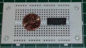
- DPST relay (on right)
The schematic below shows the relay board design. The part labeled SV1 is a 2×5 pin connector on the board. The pins labeled VCC and ENA- are the connections to the decoder/driver circuit above; ENA- connects to one of the RLY outputs. The part labeled RLY1 is the HE722A double-pole-single-throw (DPST) relay (see photo). The K+ and K- pins are the coil connections, while A1-B1 and A2-B2 connect to the pairs of contacts which are open or closed, depending on whether the coil is energized. These contacts will carry the track current whenever the contacts are closed and track voltage is present on BL_IN and WH_IN (blue and white inputs). The track power contacts are paired up to increase their current-carrying capacity.
As a visual indication, a blue LED is mounted on each relay module, which will light whenever the relay is activated.

- Relay module schematic
Connection to control processor
The required inputs to each block’s decoder/driver are the three address pins A0 through A2 and the ALL_OFF pin. (~BUS_DISABLE may be as simple as a manual switch connecting the signal to GND, so we will disregard it for now.) So we only need four logic signals to select one of up to eight power sources for each block. There are two ways to accomplish this:
- Use four of the GPIO (general-purpose input/output) pins on the processor.
- Use a port expander to add more GPIO pins controlled by the processor and use four of those.
Since your layout will likely have many track blocks, you don’t want to use up four GPIO pins for each block, or you will run out of pins quickly. If you have a processor with a lot of pins like an Arduino Mega and not a lot of blocks, say half a dozen, you could get away with option 1.
I will be using option 2, connecting the decoders to port expanders. A port expander connects to a processor through one of its existing interfaces, either I²C (2 wires) or SPI (4 wires). It then provides additional GPIO pins which can be used as either inputs or outputs under the processor’s control. I have used two different port expander devices in testing:
- The PCF8574 is an I2C port expander which adds 8 GPIO pins accessible on a single bus address; 8 different addresses can be selected per expander chip, so a bus can add 64 GPIO pins with 8 chips.
- THE MCP23017 is also an I2C port expander, but with 16 GPIO pins per chip. Again, 8 different addresses can be used, so 128 added GPIO pins are possible on a single bus. (There is also a SPI version of this device, the MCP23S17, but I’m using the I2C version.)
The MCP23017 expander’s 16 GPIO pins can control 4 relay blocks per device. With 8 available bus addresses for the expander chip, I’ll be able to control up to 32 track blocks with a single I²C bus. If I ever need more than that, an I2C multiplexer device such as the TCA9548A (see Block addressing logic above) will expand a single bus to 8 individually addressable buses, giving the potential of controlling 256 blocks. The TCA9548A multiplexer can itself support 8 different bus addresses, so by using 8 such devices on a single I2C bus, up to 64 buses can be generated, each controlling up to 32 blocks.
Software
The source files for the relay matrix controller, which receives the UDP datagrams and writes to the port expanders, are stored on GitHub.
MCP23017 library
Adafruit has an Arduino library for the MCP23017 I²C port expander which can be downloaded from GitHub here. This library provides the Adafruit_MCP23017 C++ class which handles direct access to the expander IC across the I²C bus.
BlockControl class
The BlockControl class wraps the Adafruit_MCP23017 class to divide the 16 GPIO pins of the port expander into four groups of four pins to drive the decoder/driver circuits.
BlockControl(Adafruit_MCP23017& mcp, const byte addr)
The constructor assigns a BlockControl object to a specific port expander device at a specific address, 0 through 7 (I²C address 32 (0x20) through 39 (0x27)).
void begin()
This method must be called after the constructor, and before any read or write operations can be performed. It should be called in the Arduino setup() function.
void write(const byte chan, const byte bits)
This method sets one group of 4 GPIO pins to the pattern in the low 4 bits of the bits argument. Argument chan selects the group of pins.
| chan | GPIO bits | GPIO pins |
| 0 | 3, 2, 1, 0 | 24, 23, 22, 21 |
| 1 | 7, 6, 5, 4 | 28, 27, 26, 25 |
| 2 | 11, 10, 9, 8 | 4, 3, 2, 1 |
| 3 | 15, 14, 13, 12 | 8, 7, 6, 5 |

Each channel of 4 outputs (bits 0 through 3) is meant to drive the A0, A1, A2, and ALL_OFF inputs respectively of a single block’s 74HC238 decoder (refer to Relay decoder/driver above). Each MCP23017 can control up to 4 decoders. (The A0, A1, and A2 inputs of the MCP23017 itself are used to set the device’s I2C address, 0x20 through 0x27.)
byte read(const byte chan)
This method gets the state of one group of 4 GPIO pins, using the same chan argument from the table above to select the pins.
Block class
The Block class inherits from the StateMachine class, and provides the interface specific to the block switching application.
Block(BlockControl& ctrl, const byte chan)
The constructor assigns a Block object to one of the four ports (argument chan) of a specific BlockControl object ctrl, which in turn is associated with a MCP23017 at a specific I²C address. The chan argument must be 0, 1, 2, or 3.
virtual bool update()
This method overrides the StateMachine::update method and needs to be called in each pass through the Arduino loop() function.
void enable(const bool ena)
This method sets the state of the attached block decoder’s ALL_OFF signal. If argument ena is true, ALL_OFF is set low and the decoder is enabled; if false, ALL_OFF is set high and the decoder is disabled, turning off all relays in that group.
void select(const byte sel)
This method sets the state of the attached block decoder’s A2, A1, and A0 signals, selecting which output will be active as long as the ALL_OFF signal is low. If sel is 0, decoder output 0 will go high; if sel is 1, decoder output 1 will be high; and so on. Note that only the low 3 bits of sel are used, the high 5 bits are ignored.
| sel | A2 | A1 | A0 | Relay closed |
| 0 | L | L | L | 0 |
| 1 | L | L | H | 1 |
| 2 | L | H | L | 2 |
| 3 | L | H | H | 3 |
| 4 | H | L | L | 4 |
| 5 | H | L | H | 5 |
| 6 | H | H | L | 6 |
| 7 | H | H | H | 7 |
Timing requirement for relays
The datasheet for the HE722A relays states maximum operate and release times of 1 millisecond. This means if the decoder were to switch immediately from one output on to a different one, there will be a short interval where both relays may be closed, violating the one-connection-at-a-time requirement. To prevent this, the Block class switches from one output to the next by first disabling the decoder for 10 milliseconds, then changing the selected output and re-enabling the decoder in one step.
つづく
