Background for version 1
This page describes version 1 of my hardware design for my switch machine controllers; it’s here for archive purposes only. You can find the new hardware design described here.
Schematics
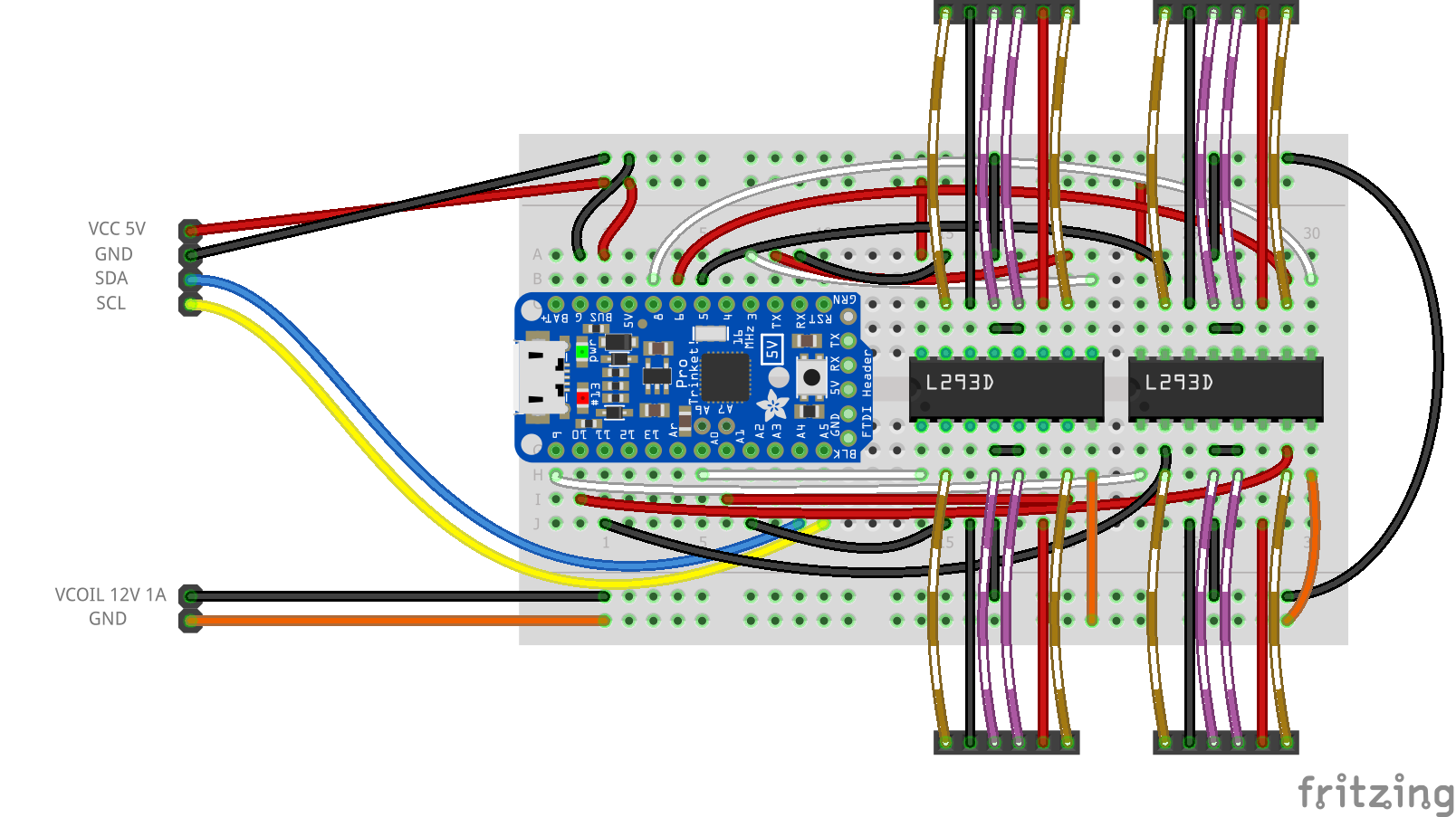
Below are diagrams of the circuit I tested above, and will be committing to hardware soon. The first is a breadboard drawing of the Adafruit Pro Trinket 5V connected to a pair of L293D drivers; each driver can power two KATO switch machines, for a total of 4 turnouts per Pro Trinket. Each turnout has a black/red wire pair (you can see them in the picture at the top of this page), which connects to two of the six pins on each 6-pin connector. The other four pins can be used to drive a pair of LEDS (like I did in the video above) to show the position to which the points were last thrown by the switch machine controller. Those pins are shown with banded wires.
The 4-pin connector in the upper left corner is the 5-volt power supply connection plus the two wires of the I2C with which a central processor communicates with the switch machine controller. (More about this in the Software section below.) The 2-pin connector in the lower left corner is the 12-volt power source which will drive the switch machines’ coils. This supply must be able to source enough current to throw the turnouts, which for the KATO turnouts is about 0.6 amperes. A 1-ampere supply will work well. Note that the two supply grounds are connected.
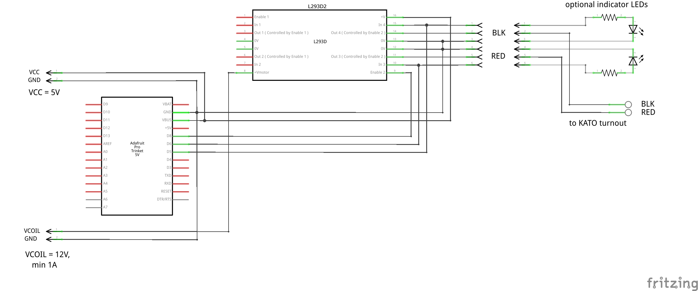
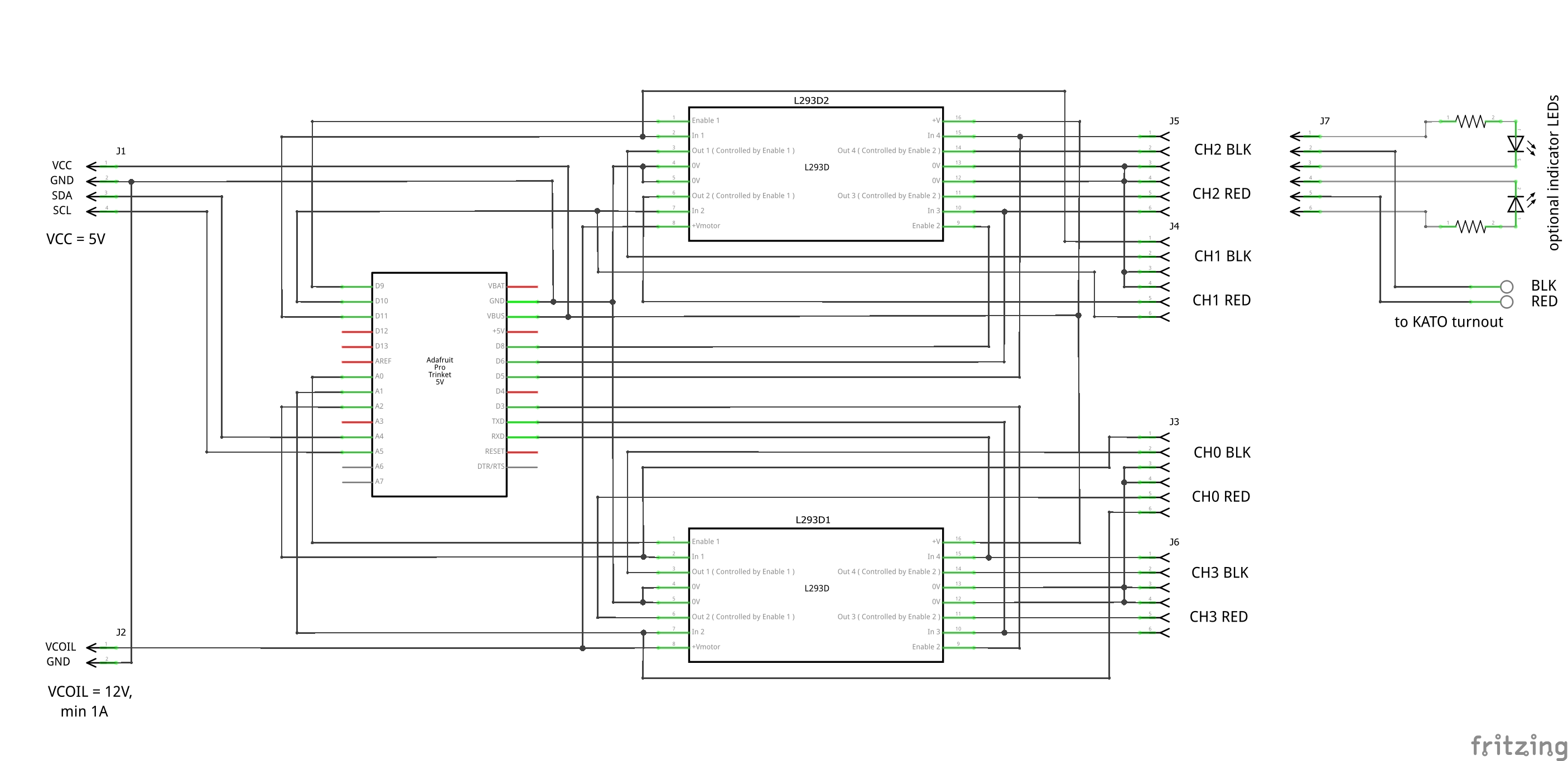
The next diagram is the circuit schematic. It includes an example of how the turnout’s wires and optional indicator LEDs are connected to each of the four 6-pin connectors. Obviously this design can be simplified to one, two, or three turnouts, with or without the LEDs. Any three digital I/O pins on the Arduino-type processor can be used to drive one half of a L293D driver. Two pins set the polarity of the pulse which will be driven through the coil (one +, one -), and the third wire (white in the drawing above) pulses the drivers to throw the points one way or the other.
To make the schematic easier to follow, here’s a single-channel version of the same circuit. I’ve also removed the I2C connection, because you might want to use something simpler like pushbuttons to operate your turnout.