
Background for version 2
This page describes a new design for my switch machine controllers. Click here for an archive of the version 1 design.
Model railroad turnouts can be either thrown manually (by Big Giant Finger) or electro-mechanically with a switch machine. Many commercially available turnouts support both. There are also many varieties of switch machines, using either slow-speed DC motors, servo motors, or solenoids. Since I’m only controlling KATO Unitrack turnouts, which have built-in solenoid switch machines, I only have to design one type of switch machine controller.
Switch machines
The KATO switch machines are one of the simplest designs available. They use a solenoid, which is a coil of thin wire connected to an external two-conductor wire. Inside the coil is a thin bar magnet which is free to slide from one end of the coil to the other, depending which way electric current flows through the coil. An internal linkage connects the bar magnet to the moving points between the rails of the turnout, so energizing the coil with 12 volts of one polarity or the other throws the points either towards the main or the siding route. There’s also a small black sliding lever alongside the turnout’s points that allows a Big Giant Finger to throw the turnout.
The most important detail about electrically controlling a solenoid switch machine is this:
You must only drive the solenoid with a pulsed current.
In other words, a solenoid should be energized for only a short interval, just long enough to toggle the solenoid to its new position. The reason is that the solenoid coil requires a full 12 volts DC through the coil’s low electrical resistance, which means a relatively high current and therefore a lot of power to be dissipated as heat in the coil. For the KATO switch machines, the coils only have about 20 ohms of resistance. If you apply 12 volts across 20 ohms, you’re dissipating a bit over 7 watts of power. That’s about the same as the power used by one of the old screw-in type C9 incandescent light bulbs that you still see on some Christmas trees… and you probably know how hot those get after they’re lit up for a minute or two. If you try powering a switch machine continuously with 12 volts, it will probably last only a few seconds before the coil wire melts.
So the key to properly operating a solenoid switch machine is to apply a pulse of 12 volts for only a fraction of a second. How long is long enough will require some experimentation to determine.
Hardware
Now 12 volts at 0.6 amperes of current (12 volts ÷ 20 ohms) is way out of range on both measures for what microcontrollers like Arduinos can drive (which is 5 volts at 0.02 amperes max). So we need some “driver” circuitry which can be triggered by an Arduino’s digital outputs to switch on and off the 12 volts needed by a switch machine. Fortunately, there are plenty of driver integrated circuits available that will do the job. For this project I’ll be using two types of driver devices, each of which can operate a pair of switch machines.
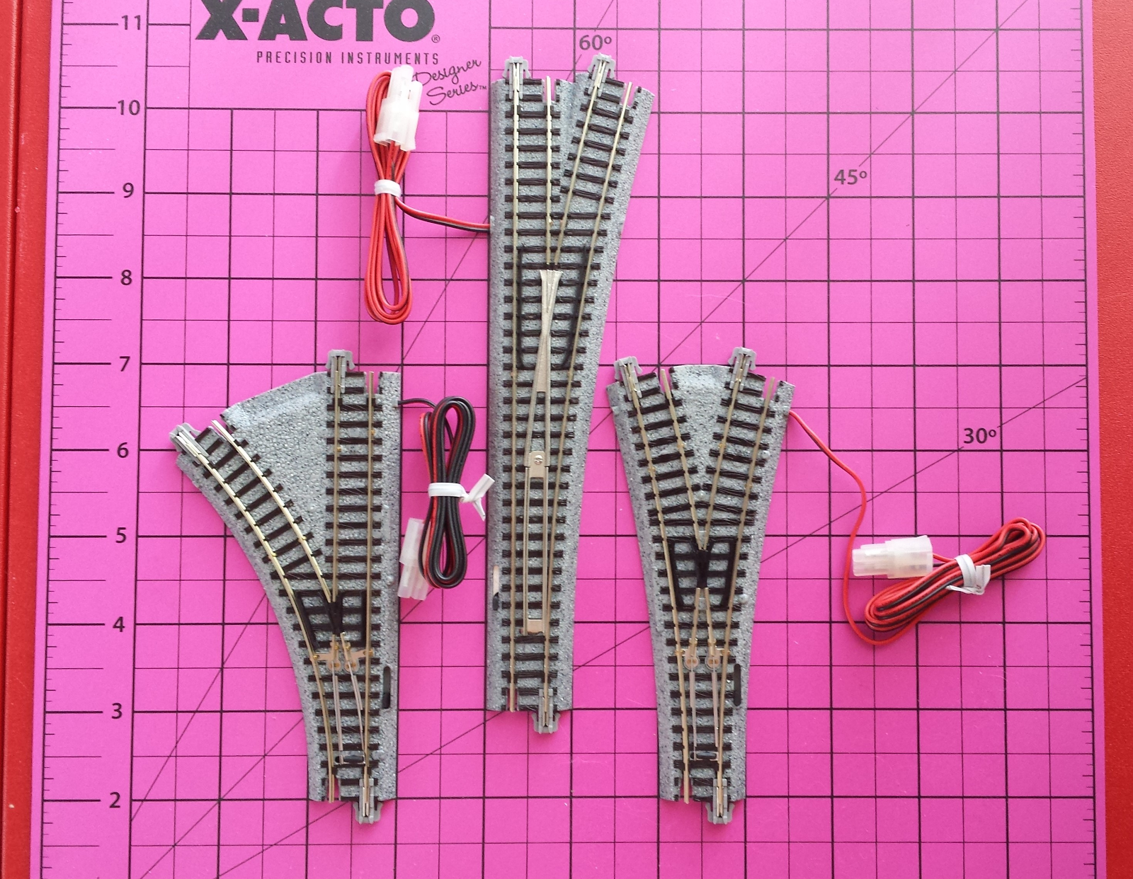
For those turnouts with a single coil in the circuit, I can use an L293D driver integrated circuit. The solenoid coils in KATO turnouts have 20 ohms resistance, so driving one coil with 12 volts draws 0.6 amps of current; the L293D can handle pulses up to 1.2 amps.
For one type of track section which has multiple coils, I need to use a TB6612 driver breakout board (BOB), because this part can drive higher current loads. The KATO double-crossover section has four coils in parallel, making the effective resistance only 5 ohms, thus making the current draw 2.4 amps. The TB6612 is rated for up to 3 amps for short pulses, so it will work fine. KATO has also released single-crossover track sections in left-hand and right-hand versions. These sections have 2 turnouts, but they are on a common linkage sharing a single solenoid, so the electrical load is the same as all the non-crossover turnouts.
- At the time I’m writing this, the L293D chip sells for about $9 per chip on Adafruit’s web site, while the TB6612 BOB goes for about $5 each on the same site. (Usually available at DigiKey as well if Adafruit is out of stock.) Since the TB6612 unit has the higher output current rating, you could just use that device for all switch machine drivers and save a few dollars. 😉
The heart of the controller is any of several types of Arduino processors. All that’s required are the two I2C pins (SDA and SCL) of the controller, plus three digital I/O pins for each turnout to be controlled. The Arduino is programmed to act as an I2C peripheral device, being controlled by a separate I2C central device, such as another Arduino or a Raspberry Pi. Multiple controllers can reside on the same I2C bus as long as each is set to a different address. I’m currently testing Adafruit Pro Trinkets (5 volt version) which are compact, inexpensive (under $10 USD), and have enough digital I/O pins to support 4 turnouts while still leaving the I2C pins available.
Update
Here’s a YouTube clip of an Arduino Micro (on the right) driving a KATO Unitrack turnout via the L293D driver chip (on the left). The minimum pulse to throw the turnout points was 10 milliseconds for this test.
The red and green LEDs show the polarity of the pulse through the turnout’s solenoid, which determines in which direction the points will move. The pulse itself is active only when the blue LED on the left is on. After some additional testing, I have doubled the pulse width to 20 milliseconds, just to make sure the points throw every time; 10 milliseconds was just barely enough, and 8 was not enough for this particular turnout.
Another update
I’ve now programmed and tested an Adafruit Pro Trinket to serve as a switch machine controller for up to four KATO switch machines, using a pair of L293D motor driver chips to drive the switch machine solenoids.
The controller will accept one-byte commands via its I2C interface from another processor (an Arduino Micro for the initial test). Each controller only responds to commands sent to its address. Each command selects one of the controller’s ports and specifies the action. When the controller receives a command, it sets the selected port’s two output pins which are connected through the driver to the switch machine, then fires a 20 millisecond pulse on a third output pin to energize the driver and move the solenoid. Since the controller knows which way it has set each attached turnout before, it’s programmed to not activate the solenoid if it’s already in the commanded position. It also knows if multiple commands have been received too quickly, to perform them in sequence so that at most one coil will be energized at any moment.
The controller also responds to 2 additional command bytes. A RESET code will set all four attached turnouts (again, in sequence) to their starting position (main). Finally, there is a REFRESH command to throw all turnouts to their already “known” positions, whether or not they are already correctly set.
The REFRESH is necessary for a couple of reasons. First, if some physical obstruction (derailed train, tiny N-gauge cat, whatever) interferes with the points actually moving, the controller has no way to detect that because there’s no feedback signal from the switch machine back to the controller. By clearing any obstruction and then sending the REFRESH command, all turnouts will be energized, and any out of position will move to the correct position. The second reason for the REFRESH command is to correct an erroneous switch position in the event a Big Giant Finger has manually operated a turnout’s small attached lever.
Schematics
(For an archive of the version 1 design, click here.)
Two features distinguish the new version of my switch machine controllers from the old one.
- A switch machine controller is now composed of two components for added flexibility: the controller module and one or more driver modules.
- The Arduino code for the controller module has been made customizable to different Arduino models.
The controller module is simply the Arduino processor with the controller code installed. In the code, you define one or more triplets of digital I/O pins, one triplet for each switch machine you will be controlling. It’s most convenient to select three immediately adjacent pins so that a standard 3-conductor servo cable can be used to connect to the driver. This design allows different Arduinos to be used. For example, the Adafruit Pro Trinket can drive 4 switch machines, just as before in version 1. An Arduino UNO can drive 5, and an Arduino Mega 2560 as many as 22. For my setups, I will use the Pro Trinkets so they can be spread out around the layout.
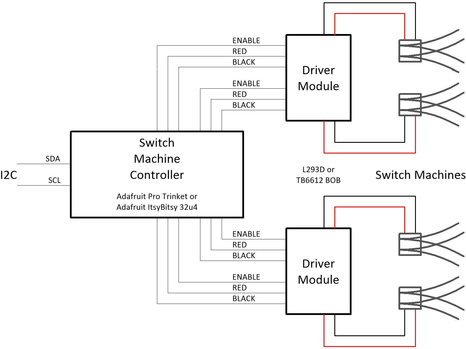
The diagram below shows how a controller module could drive a pair of driver modules, each of which can drive two switch machines.
The schematic below shows how controller modules can be tested. In this diagram, the commands to trigger actions by the controllers are sent via I2C to either controller based on the address used, either 0x30 (lower controller) or 0x31 (upper controller). The SwitchMachineController sketch running on each controller reads the three input signals labeled ADDRn:0 through ADDRn:2 to set an offset of 0 through 7, which is added to the base address of 0x30 to create the address to which the controller will respond. Tying an ADDR pin to ground sets that bit to 0, while connecting it to VCC (5 volts) sets it to 1.
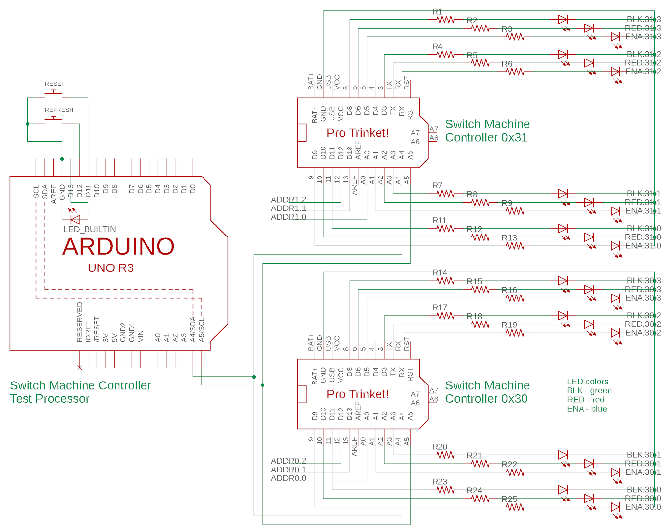
On the output side to the right, each controller drives four triplets of logic signals to control LEDs. Each triplet is a single channel which would be used to drive one half of a switch machine driver. In the test setup, a blue LED follows the “enable” signal, and red and green LEDs show the state of the “red” and “black” signals respectively. The video earlier on this page shows the same color scheme in use with a single channel being tested.
The sketch running on the Arduino UNO can be found in my repository at https://github.com/twrackers/SwitchMachineTest-sketches. The sketch running on each controller is at https://github.com/twrackers/SwitchMachineController-sketches.
In an actual layout, the LED-resistor pairs would be replaced with the inputs to switch machine drivers. Each driver module contains only the “motor driver” device, either the L293D chip or the TB6612 BOB. Each driver module can drive two switch machines, so it can be connected to one or two I/O pin triplets coming from a controller module. The driver modules share their 5-volt DC power with the controller modules, and also require a separate 12-volt DC supply to power the switch machine solenoids. If using two driver modules with the controller module above, one driver can handle any pair of the four ports, while the other driver would handle the other pair.
At the moment I have the controller and driver modules wired up on mini breadboards. I will eventually have printed circuit boards made for at least the driver modules, and possibly for the controller modules as well. See “Driver Module printed circuit boards” below.
Driver Module printed circuit boards
I succeeded in creating schematics and PCB layouts for both versions of my driver module (L293D and TB6612), and sent the files off to OSH Park (https://oshpark.com) to be turned into double-sided printed circuit boards. Here’s a picture of the component sides of the two boards.
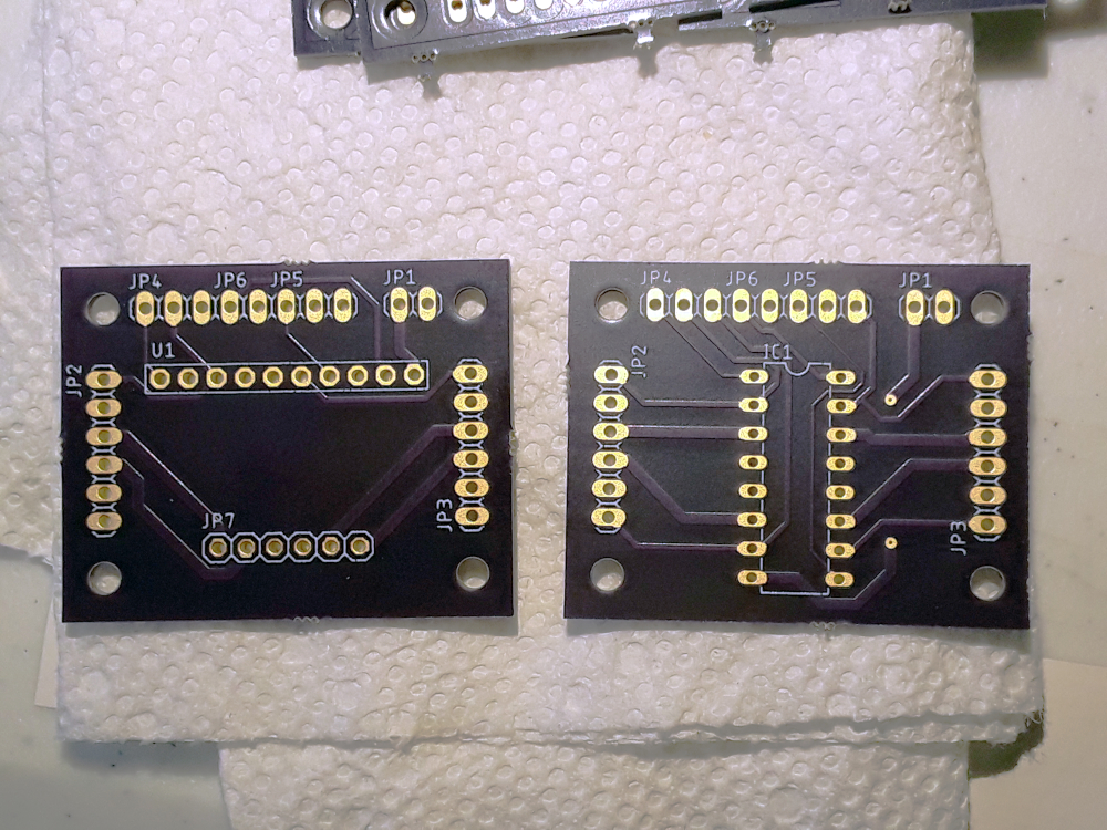
(The boards look black, but they’re actually masked in OSH Park’s signature shade of purple.) The left board is arranged to take Adafruit’s TB6612 Breakout Board (https://www.adafruit.com/product/2448), while the right one will use an L293D 16-pin IC (https://www.adafruit.com/product/807 and other sources) Here are the EAGLE schematics for both boards.
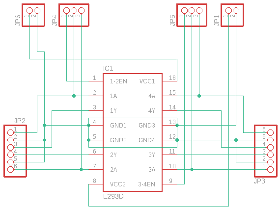

On both boards, JP6 is the connection for +5 volts and logic ground to power the logic parts of the drivers, while the +12 volts and motor ground are connected to JP1 to carry the higher currents needed to drive the solenoids.
JP4 and JP5 are a pair of 3-conductor connections coming from a controller module (or possibly two separate controllers). On each, pins 1-2-3 will connect with the white-red-black wires respectively of a servo wire, with the white wires carrying the “enable” pulses.
The two center pins on JP2 and JP3 are the connections to the switch machine coils being driven, with each pin 3 being driven by the state of the red wire coming from the controller module, and each pin 4 by the black wire. If you are only driving a switch machine with the driver, those are the only two pins you need.
Pin pairs 1-2 and 5-6 on JP2 and JP3 allow you to also connect LEDs if you want a visual indication as to which way a turnout was driven most recently (assuming the mechanism doesn’t jam and no one moves the turnout manually). I will use a green LED to indicate a turnout is thrown to its main route, and a red one for the diverging route. For each LED connection, the outermost pin (1 or 6) connects to the anode end of an LED through a series resistor (say 220 to 500 ohms), and the adjacent pin (2 or 5) is ground, connected to the LED’s cathode. With this arrangement, JP2 and JP3 can be treated as groups of three 2-pin connections.
The figure below shows where the connections to the driver boards are made. The connections to LED indicators are optional, they don’t affect operation of the driver.

Software
I’ve uploaded a SwitchMachine Arduino library to my GitHub, which can be downloaded from https://github.com/twrackers/SwitchMachine-library. (Instructions for downloading and installing this library are in the repository at https://github.com/twrackers/SwitchMachine-library/blob/main/INSTALL.md.) You can also find the Arduino sketch (application code) for my 4-channel design above at https://github.com/twrackers/SwitchMachineController-sketches. (Version 2 of the code coming soon.)
SwitchMachine library
The SwitchMachine class defines the three I/O pins on the Arduino device which will operate a single turnout through one half of the driver, either the L293D or the TB6612.
The three pins associated with a single turnout are:
- “black” and “red” pins, which will control the corresponding wires on the KATO turnout
- “enable” pin, which is pulsed to energize the driver and send current through the switch machine coil
When using servo cables (white/red/black), I will use the white wire for the enable signal, and match up the red and black wires with those on the turnout.
The polarity of the turnout’s black and red wires (one high, one low) when the enable pin is pulsed, sets the direction of the current through the coil, which determines which way the coil will move. The polarity of these wires on the KATO turnouts is standardized as follows.
| Turnout type | black HIGH, red LOW | black LOW, red HIGH |
| Left Hand | main (right) | diverging (left) |
| Right Hand | main (left) | diverging (right) |
| Wye | left | right |
| Single Crossover (LH or RH) | thru | crossover |
| Double Crossover | thru | crossover |
The SwitchMachine class is a derived class of my StateMachine class (https://github.com/twrackers/StateMachine-library). This lets the SwitchMachine code handle the timing of the enable pulse, to prevent the coil from being energized for more than 20 milliseconds. The SwitchMachine library has two constructors and two methods.
SwitchMachine(const byte enable, const byte red, const byte black);
SwitchMachine(const Triad& triad);
These constructors define a SwitchMachine object and assigns which three I/O pins are connected to one half of an L293D driver. They can either be stated explicitly (first form), or as a Triad, a triplet of bytes which is a convenient way to assign pins for multiple turnouts. The constructor is either called before or within the Arduino sketch’s setup() function.
virtual bool update();
This method is defined by all classes which are derived from the StateMachine class. This is where the timing and logic of the SwitchMachine is handled. This method should be called in the Arduino sketch’s loop() function. It returns true only when the SwitchMachine object’s state is updated. Ordinarily the user doesn’t have to worry about the returned value.
void throwPoints(const E_DIR which);
This method commands the turnout to move to the specified direction the next time an update occurs (which is why you need to call update() every time through loop()). The which parameter is one of three values.
- eMain – Throw the turnout to the main/left/thru direction as shown in the chart above.
- eDiverging – Throw the turnout to the diverging/right/crossover direction as shown in the chart above.
- eRefresh – Throw the turnout to the direction where it’s already supposed to be, based on the most recent eMain or eDiverging command. This is useful if the actual position of the points is in doubt, such as having been moved manually by human intervention.
SwitchMachineController sketch
The SwitchMachineController code supports multiple SwitchMachine objects, each with its own set of 3 I/O pins on the device. The version in the repository is written to support 4 switch machines on either an Arduino UNO or an Adafruit Pro Trinket, but can easily be customized for other devices with sufficient I/O pins and I2C support. The controller code has two main functions.
- The controller acts as an I2C peripheral device with a preset 7-bit address, and receives commands from a central processor to throw any one of its turnouts at a time.
- The controller avoids pulsing more than one turnout at a time by firing them in sequence if multiple commands are received in rapid succession. This means the 12-volt power supply only needs to drive one coil at a time.
Because each controller is an I2C peripheral with its own address, multiple controllers can share the same bus as long as their addresses are unique.
Special note: I2C over servo wire
I2C was designed to work over relatively short distances, limited by the capacitance between the conductors in the cable. For this project I am using standard white/red/black servo wire to connect the switch machine controller modules to whatever processor is sending out the commands. Assuming all the controller modules receive their 5 volt power independently of the bus, the three conductors are the two signal wires and ground. To make the capacitance between the two signal wires and the ground equal, the center wire (red) will be the ground wire. I’ve arbitrarily decided to make the white wire SDA and the black wire SCL. So far this has worked out fine over about 2 meters of servo wire. If needed, I have some I2C buffer chips which will extend the distance over which I can connect my devices.
More information about this can be found on my page here.
つづく
