
This page describes the “final” design of my Arduino-based model train throttle as it has been implemented and tested.
Overview
The throttle system consists of two required units plus a third optional one.
- The throttle unit itself provides the power for either 4 or 8 channels of track power, depending on whether one or two Motor Shields are installed. At the time I’m writing this, only one Motor Shield is in the throttle unit.
- The controller unit is the source of commands sent to the throttle unit. It can be manually operated or operate (semi-)autonomously to control the throttle unit using UDP/IP messages over Ethernet. Currently I have a manual unit which supports up to four analog joystick controls and a four-channel direction control panel.
- The power monitor unit is optional, and allows an operator to monitor the voltage outputs of the throttle unit’s 4 or 8 output channels as red or blue bargraphs; the color indicates the track polarity and thus the direction of any train being powered by that channel.
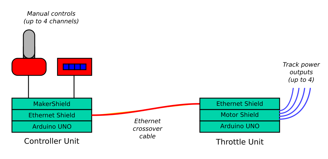
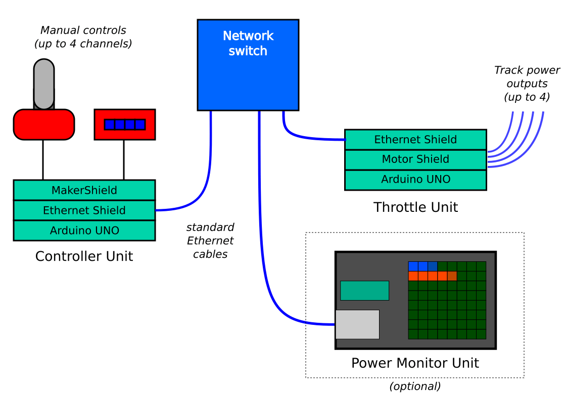
The throttle system can be set up in two distinct ways, with or without a network switch. The network switch can be omitted only if the power monitor unit is not being used. In this case, the throttle and controller units are connected by an Ethernet crossover cable (Figure 1). If a network switch is used (Figure 2), standard Ethernet cables are used, and the power monitor unit can be included or omitted.
The reason for dividing the throttle system up into units is modularity. The throttle unit is common to all configurations, and because it is connected by Ethernet to other parts of the overall model railroad system, I can use whatever type of controller unit I wish, manual or automatic such as by a Raspberry Pi. In fact, because UDP/IP is used for communications, the throttle can respond to more than one controller at the same time, as long as multiple controllers don’t try to control the same throttle channel.
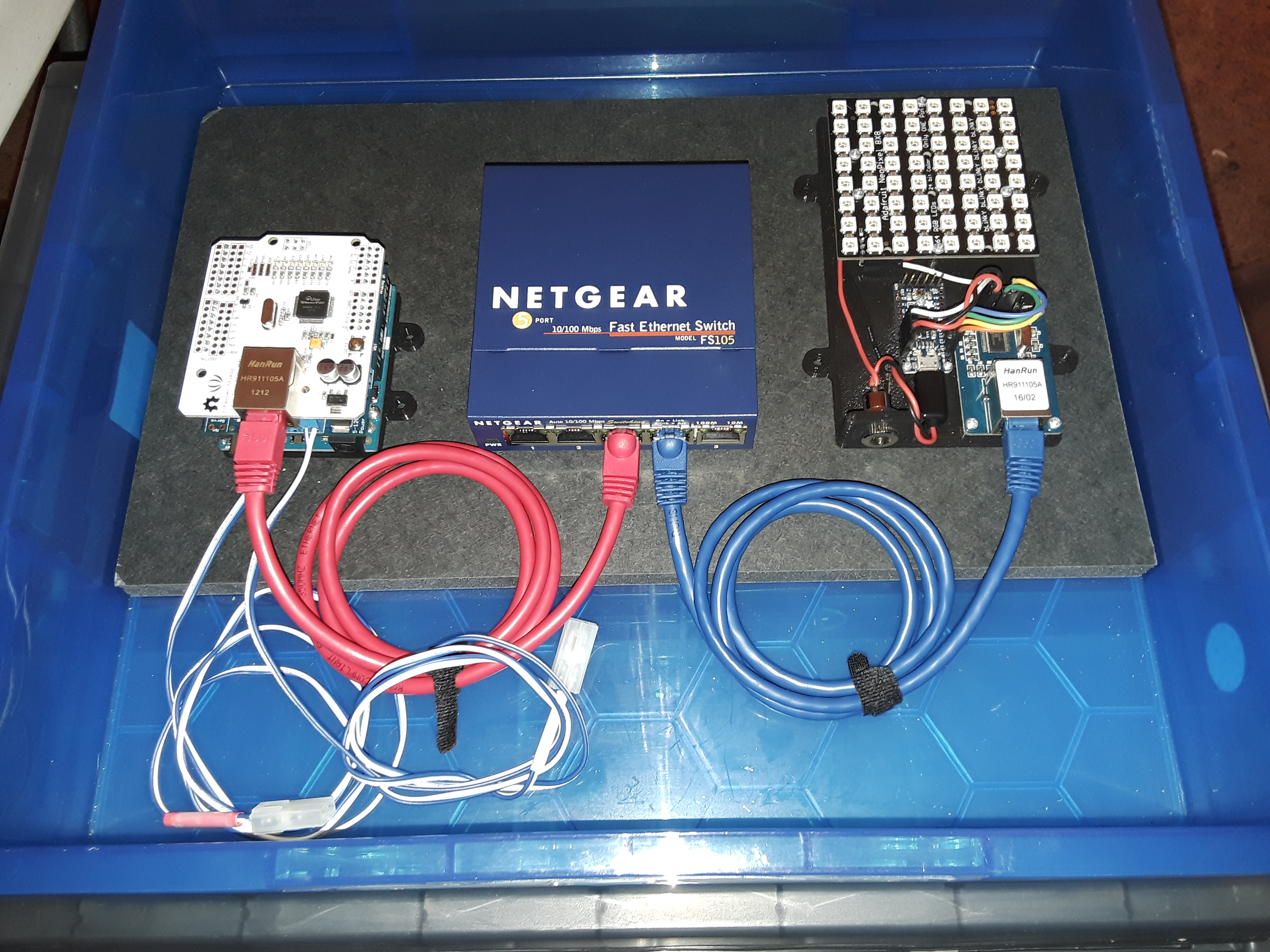
I also have flexibility in where I place the network switch and the throttle system units. In the setup in Figure 3, as used at an event in which our model train club participated, the container pictured was placed out of the way under a table, and only the controller unit was on the table by the tracks. In the long run, I expect the power monitor unit to be placed near the controller(s), and the throttle unit placed closer to the tracks.
Throttle system units
Throttle unit

The throttle unit consists of, from bottom to top:
- Arduino UNO
- Adafruit Motor Shield v2.3
- SeeedStudio Ethernet Shield v1
The Adafruit Motor Shield will drive four motors at a time. In Figure 4 you can see one of the two output terminal blocks on the Motor Shield with two track power leads (blue and white) connected. The throttle unit will support two Motor Shields, providing power to eight trains at the same time. Power to the throttle unit is provided from a 12V 5A switching power supply plugged into the Arduino’s barrel jack. At this time the Motor Shield receives its 12V power from the Arduino; eventually I will probably use its DC-input screw terminals instead, so that all power going to the trains is not being passed through the Arduino.
I will probably reconfigure the throttle unit soon, replacing the SeeedStudio version 1 Ethernet shield, based on the WizNet W5100 chipset, with a newer one using either the W5200 or W5500 chipset. Both of these chips support 8 simultaneous IP channels as opposed to 4 with the old one. This would expand the number of controllers which can be used at once from 3 to 7, reserving one channel for the connection to the power monitor unit. Also, the newer shields have stackable headers, so I will move the Ethernet shield to below the motor shield(s) to improve access to the motor shield screw terminals.
Controller unit
My first controller unit is a manual unit consisting of, from bottom to top (Figure 5):
- Arduino UNO
- SeeedStudio Ethernet Shield v2
- Maker Shed MakerShield prototyping board
The controller unit also uses, connected through the MakerShield (Figure 6):
- up to four APEM BF Series single-axis analog joysticks (currently have two) on 3D-printed bases
- 4-channel direction control panel, containing a 4-button membrane switch and four NeoPixels in a 3D-printed case
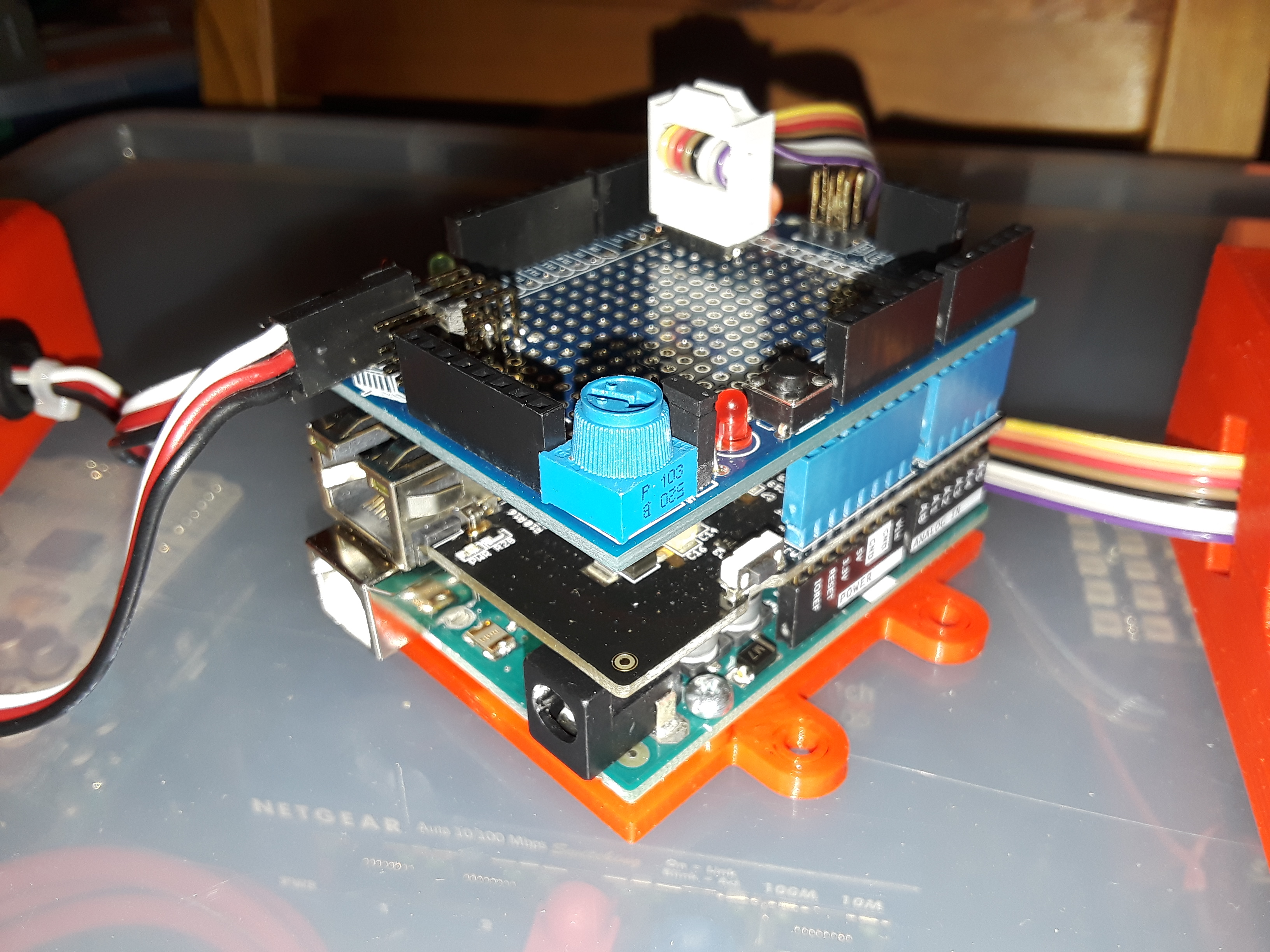
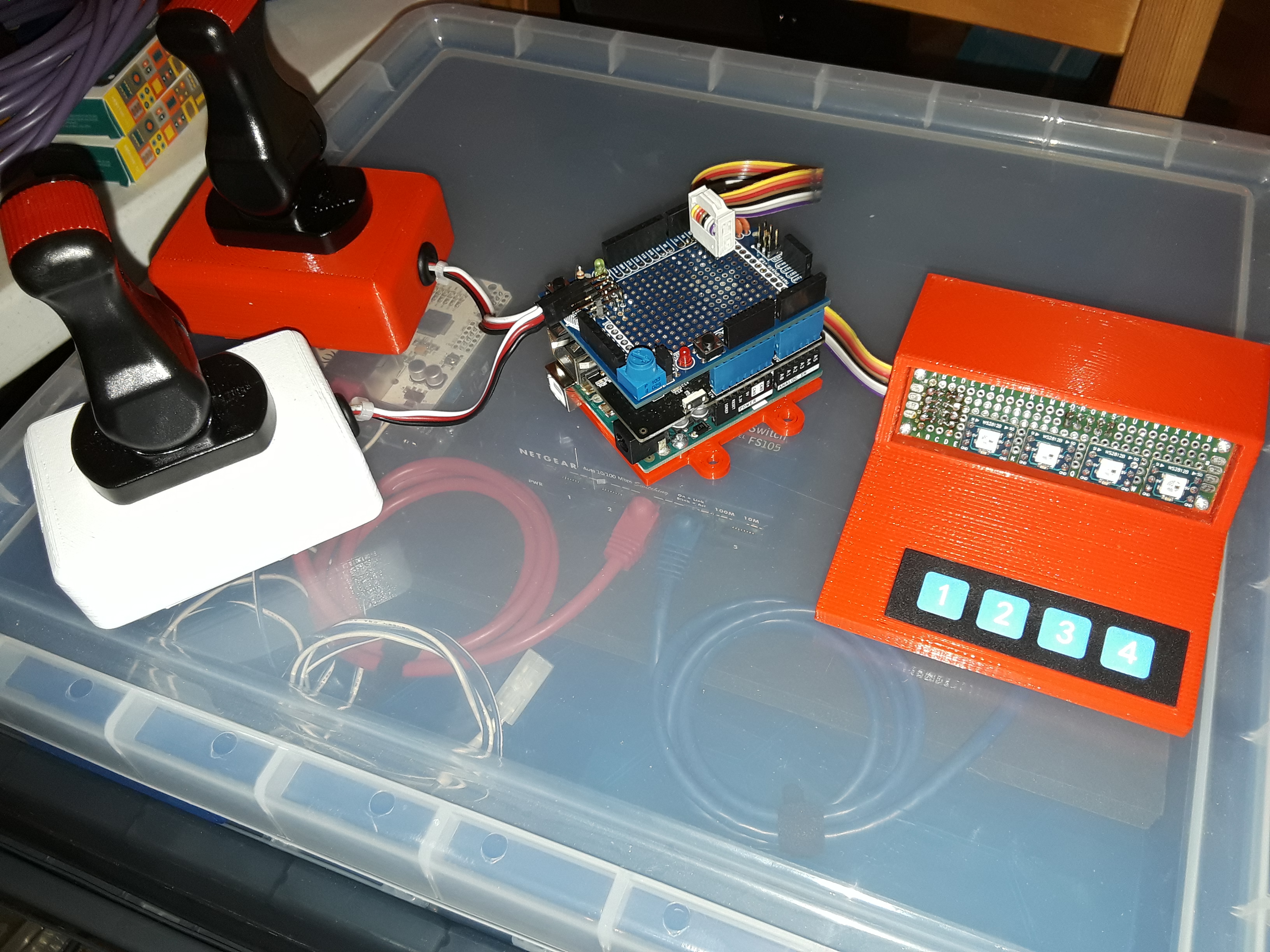
I used the MakerShield to hold the connectors to the throttle levers and the direction controls. Each throttle lever uses the same 3-pin connector that hobby servo motors and many other devices use: white (signal), red (power), black (ground). That makes it easy to use 3-wire servo extension cables to place the levers conveniently.
The direction controls are connected by an 8-conductor ribbon cable to the MakerShield. The membrane buttons on the case use one wire for ground and one for each button. The buttons connect to I/O pins on the Arduino, set to INPUT_PULLUP mode; a closed button reads as LOW, an open button as HIGH. The lights are red-green-blue NeoPixels daisy-chained together. The NeoPixels use the three remaining wires in the ribbon cable for signal, power, and ground.
Power monitor unit
{placeholder for block diagram Figure 7}
The power monitor unit consists of (Figure 8):
- Adafruit Pro Trinket 5V (center)
- ENC28J60 Ethernet module (lower right)
- Adafruit NeoPixel 8×8 LED matrix panel (top)
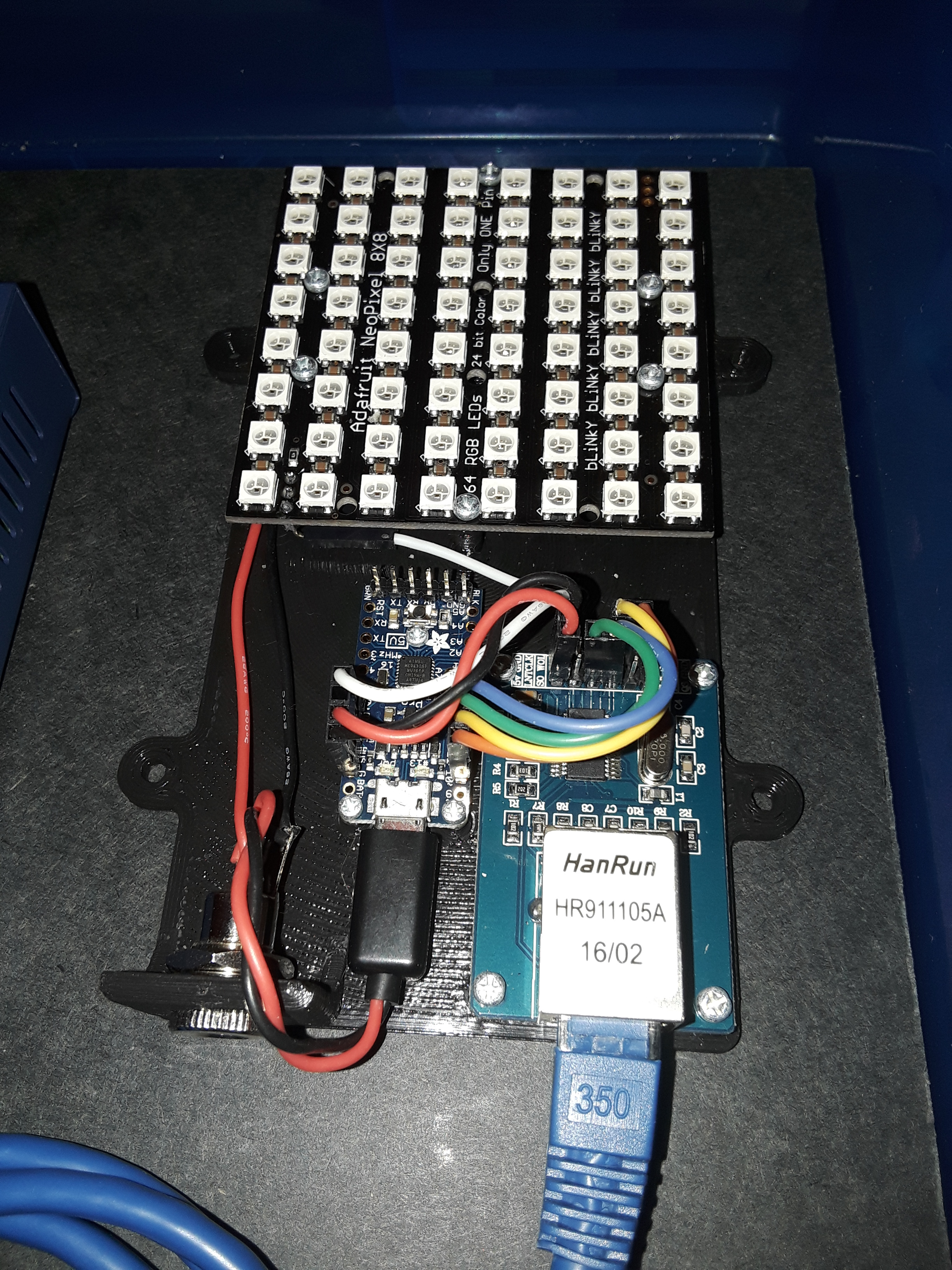
The power monitor unit receives UDP messages from the throttle unit which contain the track polarity of all eight possible throttle channels, encoded as bits in a single byte, plus eight more bytes which are the output values, 0 (off) to 255 (full power), being sent to the Motor Shield channels. Track polarity is displayed by lighting up a blue or red bargraph. Figure 2 above will give you an idea of what the bargraphs look like when illuminated. The power monitor unit serves as a visual indication of the throttle unit’s state, both during testing and eventually when the entire throttle system is part of a display at future public events such as Arduino Day, Maker events, or model train shows.
つづく
