
Quick link to GitHub repository
https://github.com/twrackers/TrackSensor-sketches
Background
The key to creating a model railroad setup which can be operated by a computer is knowing where the trains are on the track. It would be nice if we could sense each train’s position anywhere along the track at any time, but until we start incorporating time-domain reflectometers into our layouts (which is not happening anytime soon), we have to settle for either of two options:
- Sense the presence of a powered train car (motor car or lighted car) somewhere within an electrically isolated track block.
- Sense the train with some form of sensor at a specific point on the track.
For this project, I’m going with option 2 exclusively, although one could mix both options on the same layout. The sensors I’m using are infrared reflectance sensors mounted below the tracks and looking up between the rails. Up to 8 of these sensors will be connected to a sensor node, a small Arduino-class microcontroller board. Up to 16 of these sensor nodes can be connected to a sensor controller, another Arduino board. So a single sensor controller can monitor the state of as many as 128 different track sensors. The entire system will support multiple sensor controllers as well, but I doubt I’ll need to have more than one for this first project.
Sensors
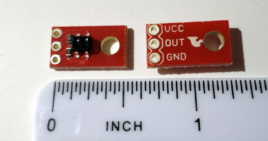
The sensor I’m planning to use is a QRE1113 line sensor breakout from SparkFun Electronics of Niwot, Colorado. It’s a small red circuit board with the sensor component mounted near the center on one side. It’s just the right size to fit under a section of KATO Unitrack with a hole drilled and filed square for the sensor element to poke up between the rail ties (sleepers in some parts of the world), with the board’s mounting hole fitting over one of the blind screw holes molded into the underside of the track sections.
The sensor element is an analog device, with the infrared (IR) emitter shining upwards and the IR detector watching for reflected IR light. When there’s no light detected, the IR detector returns a high signal, around 5 volts. If an object passes close enough in front of the sensor element, the detector returns a lower voltage; the more light detected, the lower the voltage goes. It turns out the dark gray parts of the PORTRAM undersides don’t reflect a lot of light back to the sensors, so I may put small pieces of white tape on the bottom of the trams to compensate.

Controllers and nodes
Sensor nodes
Each sensor node is a small Arduino-class microcontroller board with multiple analog input pins. Each analog input pin can be connected to a track sensor; the number of sensors supported by the node depends on which board is used. For testing, I’m using Arduino Micro boards which have 12 analog input pins; for the actual layout, I’ll be using Adafruit Pro Trinkets (5 volt variety) as the nodes, with 8 analog inputs each. I chose the Pro Trinkets because:
- 8 sensors per node was enough, and allowed the sensor to be selected with only 3 bits in a command byte.
- The Pro Trinkets are cheaper per unit (around $10 USD versus $25 for the Arduino Micro).
- At the time I made the choice, I was having trouble finding online vendors who had the Arduino Micro in stock, whereas Adafruit had Pro Trinkets available.
The sensor nodes communicate with a sensor controller using a Serial Peripheral Interface (SPI) on each Arduino. The nodes are daisy-chained so that multiple nodes share the sensor controller’s single SPI port. More detail is given in the Sensor Network section below.
Update: Adafruit now recommends that users design with their ItsyBitsy 32u4 processor board in place of the older Pro Trinket board. The ItsyBitsy board is basically the same physical size as the Pro Trinket but works better with the computers used to program it. It also has 12 analog inputs over the Pro Trinket’s 8 inputs. Both still support SPI, I2C, and serial interfaces for communications. The ItsyBitsy is also (at this time) the same price as the Pro Trinket at just under $10 USD.
Sensor controllers
Each sensor controller is connected via the SPI daisy-chain to up to 16 sensor nodes. This means that all data transfers between the controller and its nodes are initiated by the controller.
One or more sensor controllers will be connected to the central processor, such as a Raspberry Pi, via an I2C bus. Each sensor controller will have a unique I2C address, and will act as an I2C peripheral device, while the central processor will be the I2C controller device. Again, this means the central processor will initiate all data transfers between itself and the sensor controllers, but the sensor controllers will be able to interrupt the central processor to request a data transfer. Each data transfer will be a single data byte that contains:
- a sensor number connected to a node (3 bits, 0 to 7)
- the node number connected to the controller (4 bits, 0 to 15)
- whether the sensor turned on or off (1 bit, 1 for detect or 0 for no detect)
Just about any Arduino device with enough I/O pins can serve as a sensor controller. For testing, I have used an Arduino UNO, but for the actual layout I’ll probably use an Adafruit Pro Trinket or ItsyBitsy 32u4, which are much more compact and less expensive than the UNO but still have sufficient I/O pins.
Sensor network
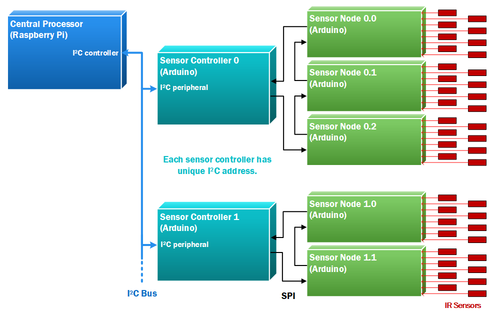
Below is a block diagram of the track sensor network, showing the various processors and the communication paths between them. Note that the flow of data via SPI from each sensor controller goes as a daisy chain from its highest-numbered sensor node down to its node 0. More information on this daisy-chain form of SPI can be found on my page on interfacing.
Here’s my first test configuration on the workbench.
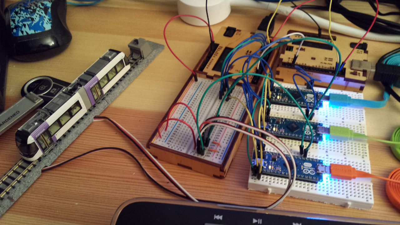
You can see to the left the first two sensor track sections with an N-gauge PORTRAM model. The three Arduino Micros with the colorful USB cables are the sensor nodes, with node 0 to the front. Node 0 is connected to the two sensors on its channels 0 and 1. Nodes 1 and 2 don’t have any sensors connected, but were used to demonstrate that daisy-chaining SPI interfaces actually works.
The two wooden cases contain Arduino UNOs; the one with its own protoboard is acting as the sensor controller, and the other is performing the work of the central processor.
Software
This section describes the Arduino sketches which run on a sensor controller and the sensor nodes attached to it.
Sensor nodes
The Arduino sketch which runs on each sensor node can be found in my GitHub repository at github.com/twrackers/TrackSensor-sketches/tree/main/TrackSensor_Node.
The TrackSensor_Node sketch starts by calibrating the outputs from the sensors when they are not detecting a reflected signal. It then sets the detection threshold for each sensor to a fixed fraction of that signal (currently 90%). Remember that infrared light reflected back to the sensor causes the sensor output to dip lower, so when the output drops below the sensor’s calibrated threshold, it is considered a detection event.
Once the sensors are calibrated, the sketch enters a fast loop (around 20 Hz) where it samples its analog inputs, masks off unused channels (more on that below), and saves the current sense/no-sense state of all channels.
The sensor node also has an interrupt handler which takes control briefly when the SPI interface’s CS (Chip Select) pin, driven by the sensor controller, changes state to start or complete an SPI data transfer.
Sensor controller
The Arduino sketch which runs on each sensor controller can be found in my GitHub repository at github.com/twrackers/TrackSensor-sketches/tree/main/TrackSensor_Controller.
Each sensor node is connected via its SPI interface, possibly daisy-chained with additional sensor nodes, to a sensor controller. The sensor controller periodically performs a data transfer of mask bytes into the sensor nodes, and at the same time receives the sensor status bytes from the nodes. It then determines which node channels changed state between sense and no-sense, and queues up event bytes which will be sent to the central controller via the I2C bus. Each event byte contains the node number (0 to 15), its channel number (0 to 7), and whether the sensor’s new state is sense or no-sense.
The purpose of the mask byte passed to each node is to set which of the node’s channels will be monitored. A channel that is masked off will always return the no-sense state. At startup, the TrackSensor_Controller sketch uses these mask bytes to count how many nodes are connected to its daisy chain. The central processor will then read the node count from each sensor controller to verify that the track sensor network has started up correctly. You can read an explanation of how the node counting is done in the source files in the GitHub repository above.
