
In a discussion today with other members of our model railroad club (http://japanrailmodelers.org), we talked for a while about how T-TRAK modules can be wired to support the addition of a power harness or power bus so that track power doesn’t have to be carried only by the rails and the rail joiners where track sections meet. I said I’d post some pictures of how I do it, so here they are.
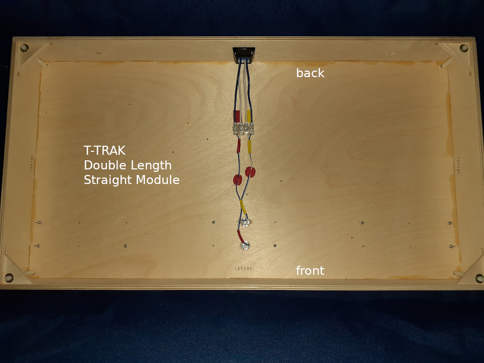
Figure 1 is a view from underneath a standard double-length straight T-TRAK module, assembled from a Masterpiece Modules kit. In the corners are nylon threaded leveling legs mounted in brass threaded inserts. You can see two rows of pre-drilled holes for attaching the KATO Unitrack (on the top surface) with small track screws. The photos below zoom in on the details of how I do the wiring.
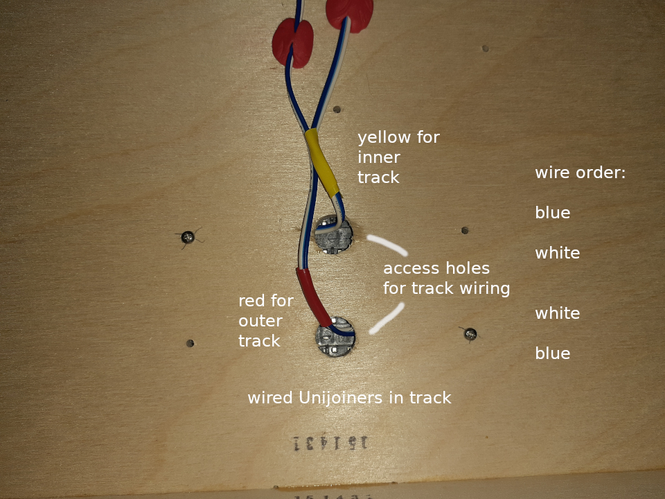
I drilled out two larger holes to pass the wires through. Each track uses a pair of wired Unijoiners for its power connection. These joiners come in pairs, one with a blue wire and one with a white one. The T-TRAK “standard” says that the wire order from front to back (or back to front) should be blue-white-white-blue. It also recommends the wiring for the outer (toward the front) track should be marked in red, and the inner track (toward the back) should be tagged with yellow. I used short lengths of heat-shrink tubing for this.
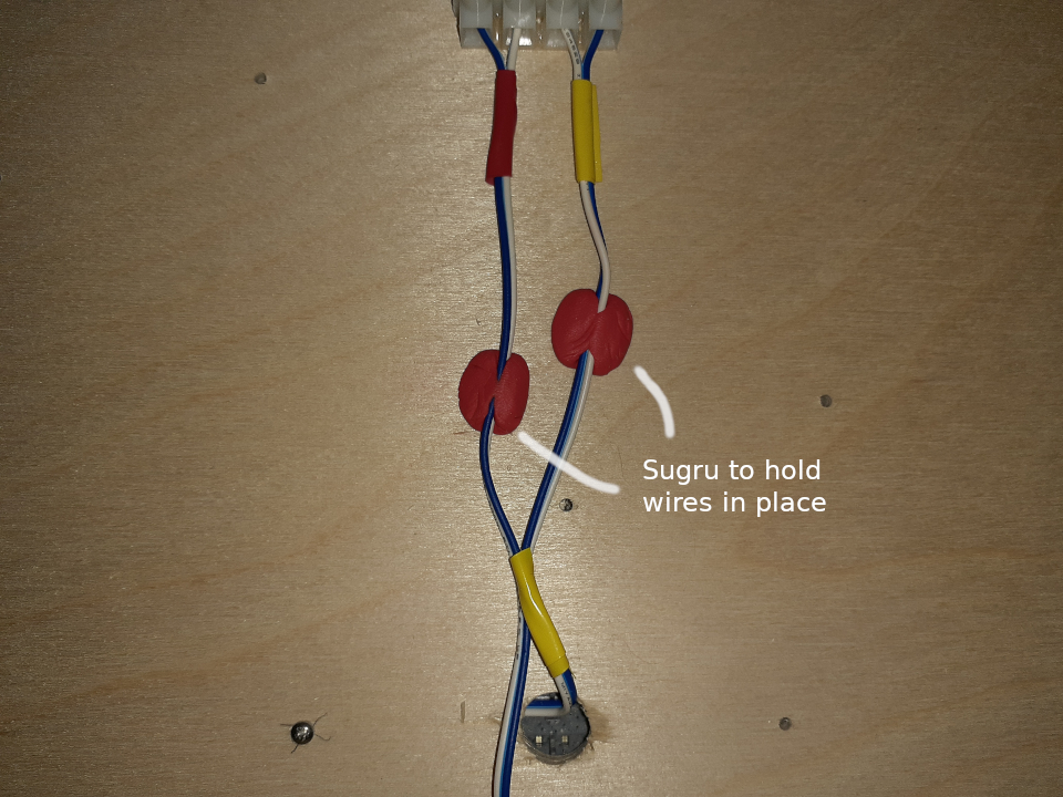
It’s a good practice to tack down any wires that might dangle to prevent snagging on anything. It also looks better if you don’t have droopy wires. I used a clump of Sugru molded around each wire pair, smooshed against the surface, then allowed to cure overnight. Since Sugru cures into rubber, you can always cut it away if you need to change or remove it.
Be warned: Sugru only has a shelf life of about 13 months at room temperature. Storing it in your fridge or freezer can triple that shelf life. Just warm it back up before you use it.
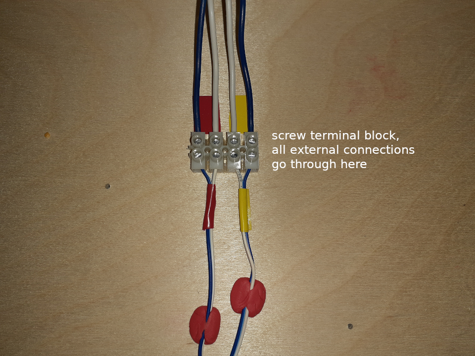
A connector block lets you join the thin KATO blue-white wires to stiffer 16 or 18 gauge wires. I used blue and white wires here too, just to be consistent. The shorter and thicker wires won’t droop like the thinner wires can, so no Sugru is needed here.
If you decide you want to use the same Tamiya (sp?) connectors KATO uses with their wiring, throttles, and such, this is a good place to connect them. If they get pulled and broken, you can just replace them.
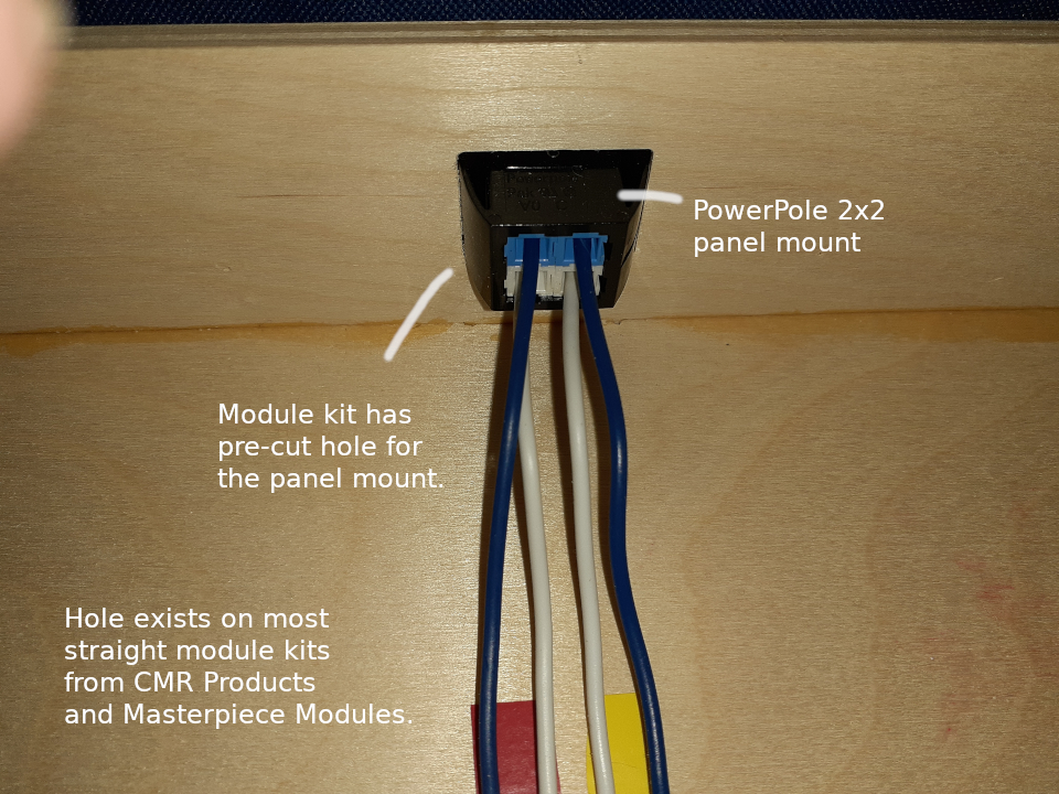
Both makers of T-TRAK modules which I’ve used put a 1½ x 2 inch on the back panel of many of their modules, which is the same size required by a 2×2 PowerPole panel mount block. I prefer PowerPole connectors over KATO’s Tamiya connectors. But if I need to connect my modules to a power harness using Tamiya connectors, I can just whip up 4-wire pigtails to adapt these PowerPoles to the Tamiya-based harness.
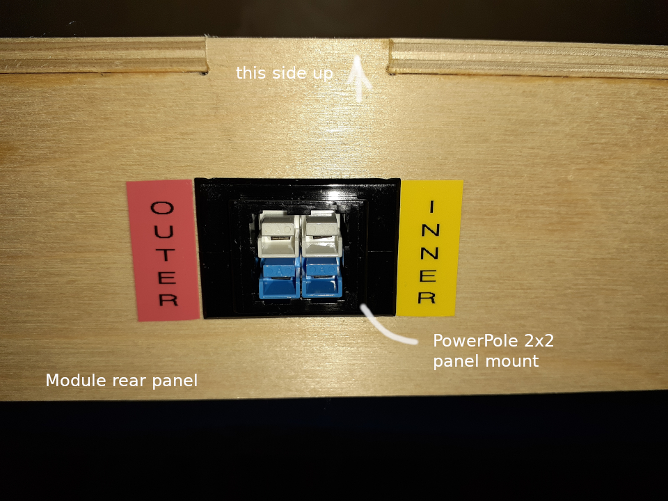
Figure 6 is the view of the PowerPoles from the outside of the module. I use a Brother label printer with red and yellow tape cartridges to mark the outer (front) and inner (rear) connector pairs.
