
Background
One interesting and useful piece of model railroading equipment is the train speedometer, a device which will measure the scale speed of a model train rolling past it or through it, depending on the design and its intended use. There are some commercially available speedometer devices on the market, none of which I’ve actually used.
However, I’ve recently begun doing short presentations related to using Arduinos in model railroading on some of the monthly NRail ZoomTRAK online meetings. This past summer one of the organizers asked me about using Arduinos to create train speedometers, and that sounded like an interesting project to cover in an upcoming ZoomTRAK. With about a month’s worth of tinkering, coding, and testing, I was able to piece together one that works. I presented on the September ZoomTRAK, of which a recording has been posted on YouTube. The presentation was fairly condensed, so I will present more details on the design on this page.
What you need
In order to develop a train speedometer, you need at least the following.
- The scale of the model train whose speed you will be measuring.
- The units of speed you want.
- Two identical sensors to detect the passage of the train.
- The distance between the two sensors.
- The elapsed time the train takes passing from one sensor to the other.
Scale factor
Obviously, you need to know the scale of the railroad on which you’ll be clocking the passing trains. For HO scale in the US (1:87 scale or 1:87.1, depending on whom you ask), the scale factor is 87 or 87.1. N scale in the US would use a scale factor of 160, while Japanese model trains are either 1:160 scale (shinkansen trains) or 1:150 (all non-shinkansen).
Units of speed
What units of speed do you want to display? In the US and UK, miles-per-hour (mi/hr or mph) is used, while in most other countries kilometers-per-hour (km/hr) is how speeds are written.
Sensors
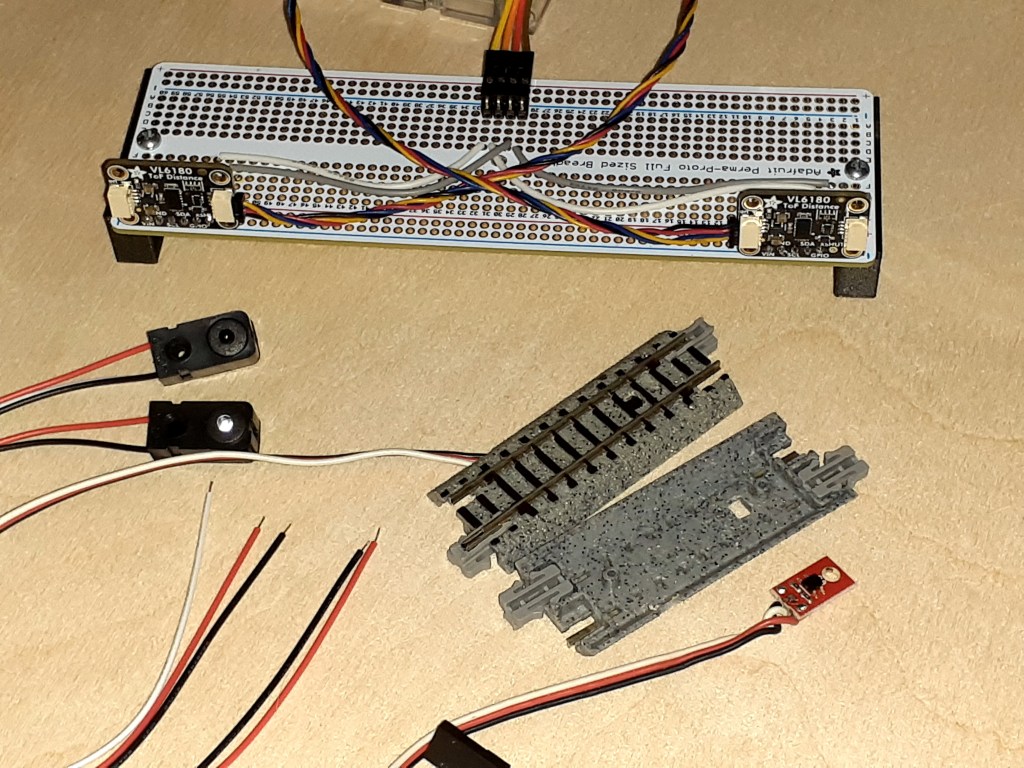
Nearly all sensors used for train speedometers are optical sensors, which neither make contact with the passing train nor are electrically or physically connected to the rails on which the trains are rolling. Figure 1 shows some examples.
The most commonly available optical sensors are:
- Beam-break emitter/detector pairs, which watch for a train passing between them and blocking the beam of light passing between them. (See Figure 2 below.)
- Reflective sensors place the emitter and detector either side-by-side, or physically inside the same component. These sensors watch for the emitter’s light to reflect back from the passing train into the detector. (See Figure 3 below.)
- Time-of-flight (ToF) distance measuring sensors are more sophisticated devices, basically miniature LIDAR (LIght Detection And Ranging) devices. Think of LIDAR as being just like RADAR, except using light instead of radio waves. ToF sensors emit pulses of light from a tiny laser and measure the time each pulse takes to reflect off a target and arrive back at the sensor’s detector. Unlike the reflective sensors, ToF sensors do not measure the intensity of the reflected light but the distance to the reflecting object. More on this below. (See Figure 4 below.)


Sensor separation
The speedometer needs the distance between the two sensors in order to calculate speed. This can either be in decimal inches or metric units; my preference is in millimeters.
Elapsed time between sensor detections
This is the most important piece of information your train speedometer requires, as this will change from one passage of a train to the next. High precision (number of decimal places) and high accuracy (closeness to reality) are both desirable to get good results.
Basics of operation
The speedometer requires the two sensors be mounted in the same manner and distance from the track which will be watched for passing trains. The sensors will be connected to inputs on the time measuring device, which in this project is an Arduino class microcontroller. The Arduino code will use an internal clock which starts at zero upon reset and counts up 1,000 times per second. By reading this clock twice and subtracting the first reading from the second, you have the number of milliseconds that passed between reads.
Each sensor’s output, once processed by code in the Arduino, becomes either a DETECT or a NO-DETECT value. What the speedometer needs to do is measure the time from when one sensor goes from NO-DETECT to DETECT, to when the other sensor does the same. For this discussion, let’s just call the sensor outputs A and B, and an output is TRUE if it is detecting a train and FALSE if it is not.
Below is a very simplified state diagram to show the basic logic followed by the speedometer. In this diagram, “millis()” is the Arduino function used to read the millisecond clock.
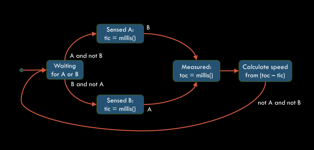
Starting at the left side, the speedometer code repeatedly checks if either sensor A or B detects an object (our train). As soon as one sensor only, either A or B, DETECTs the train, the code shifts from Waiting to either Sensed A or Sensed B, and marks the current clock time (which we’ll call tic). The code then repeatedly checks only the other sensor until it too DETECTs the train. The code shifts to Measured and reads the clock time again (called toc). From the difference in the two clock readings. toc – tic, the scale speed can now be calculated and displayed. Finally, the code will not return to the Waiting state until both sensors return to their NO-DETECT states.
Calculating scale speed
Once the time between detections by the sensors has been measured, the scale speed to be displayed can be calculated. We already have the sensor separation which is constant, while the scale factor and desired speed units could be switchable.
First, we’ve already calculated the elapsed time with
elapsed_time [msec] = toc - ticThe actual speed of the train is calculated by
    actual_speed [mm/sec] = sensor_separation [mm]
                          x (1000 msec / 1 sec) / elapsed_time [msec]
The scale speed is then calculated with
    scale_speed [km/hr] = actual_speed [mm/sec] x (1 km / 1,000,000 mm)
                        x (3,600 sec / 1 hr) x scale_factor
or
    scale_speed [mph] = actual_speed [mm/sec] x (1 mile / 1,609,344 mm)
                      x (3,600 sec / 1 hr) x scale_factor
where scale_factor is 87 for HO scale, 160 for US N scale, or whatever is correct for the scale you are using. We now have the scale speed which can be displayed.
For those readers who are savvy in reading C++ code, here’s actual code which does these calculations. The variables whose names begin with m_ are data members of the Speedometer class.
// Conversion factor, kilometers to miles
#define MI_PER_KM (0.62137119224)

// Calculate speed from:
//   dt_msec: elapsed time (msec)
//   m_spacing: sensor spacing (mm)
//   m_scale: scale factor (87, 150, 160, …)
//   m_metric: true for km/hr, false for mi/hr
double Speedometer::calcScaleSpeed(const uint32_t dt_msec) const {
  // Calculate measured speed in mm/msec, same as m/sec.
  double meas_speed = (double) m_spacing / (double) dt_msec;
  // Calculate scale speed in scale meters per second.
  double scale_speed = meas_speed * (double) m_scale;
  // Convert scale speed to scale km/hr.
  double km_per_hr = scale_speed * 3.6;
  // Return scale speed in km/hr, or convert to mi/hr.
  return km_per_hr * (m_metric ? 1.0 : MI_PER_KM);
}
つづく
